
Part 1 of this FAQ looked at the basics of the 20-mA current loop, why it is still used extensively, and its primary attributes. In this part, we’ll look at how the analog current loop is used for digitized signals and at self-powered loops – two developments which have extended its life and viability.
Q: How can the analog current loop adapt to the digital world?
A: The obvious way, as noted in Part 1, is to use the current to represent a digitized signal rather than an analog one. This is the first step toward extending the use of the analog current to digital settings: digitizing the sensor signal or signal directing the actuator, and using that in place of the proportional analog signal. Typical digital resolution is between 12 and 16 bits; 18-bit is needed only in unusual cases, as most industrial systems do not need more than 16-bit performance, and the sensor/actuator itself may not offer resolution beyond 16 bits.
Q: Then what happens?
A: Just digitizing a signal does not realize the full potential of a digitized signal and corresponding arrangement. But there are issues with telling the users of these bits where the bit field starts and ends, add error detection, and provide the other functions and features that the digital format and protocol either can support or require.
Q: How was the simple but inadequate basic digitization technique improved?
A: It was done via the establishment of a comprehensive standard which takes the basic digitized bits and adds format and protocol aspects such a multibyte preamble, start byte, multibyte address, command filed, data field, a field indicating the number of data bytes, the actual data, and finally, a checksum.
This standard was initiated by Rosemount Corp in the 1980s and soon became the de facto standard. It was formalized with the HART (Highway Addressable Remote Transducer) designation in the 1990s and became an “open” standard, and even has an IEC designation for use in Europe. It has undergone three major revisions yet preserved backward compatibility with all prior releases – an important benefit for the industrial market, where PC-like upgrades and subsequent incompatibilities are not acceptable due to the disruption they cause, even though they may be tolerated in the consumer and office markets.
As an additional feature, the HART command field includes a number which identifies the manufacturer of the associated electronics. This is a major benefit in installation, debugging, documentation, and reducing confusion, as there are well over 100 vendors of HART-compatible devices.
Q: Other than adding a format and protocol standard, what does HART do to update the 20-mA loop?
A: The use of an address byte field allows a single loop to serve multiple sensors and actuators, as each transducer can be assigned a unique number. This results in a significant saving in wiring effort and installation cost, compared to one loop/transducer arrangement.
While using a single loop for many transducers means that the potential throughput rate per transducer is reduced since the loop is shared among the many transducers, this is generally not a problem. The reality is that in most industrial applications, data updates and commands occur fairly slowly, on the order of once per second. For example, temperature – the most-frequently measured physical variable– does not change rapidly, especially if the thermal mass is large.
Q: So, the HART standard has allowed the 20-mA current loop to exist in the digital age. Are there any other improvements which can keep the loop very viable?
A: Yes, the other major enhancement is on the analog/power side. Recall that each loop uses 4-20 mA as the signaling range, using a controllable current at the sensor transmitter or actuator receiver. However, each transmitter still needs an additional power source to power its own electronics which perform signal conditioning, scaling, A/D converter, and current driver for a sensor, or the complement for an actuator. This supply adds to cost and installation challenges.
However, as IC technology has progressed to ever-lower power operation for the transmitter circuitry (or for the receiver), the concept of loop-powered transmitters and receivers became a reality. Here, all the electronics associated with the sensor or actuator has a self-operating current requirement of under 4 mA, and therefore no additional power source is needed. As long as the loop voltage (also called the compliance voltage), is high enough, the loop interface can be powered by the loop itself.
Q: Is there any other advantage to a loop-powered interface?
A: Yes. Many loop-powered devices need to have approval for use in hazardous areas as either non-incendive (N.I.) or intrinsically safe (I.S.). For either of these approvals require, the electronics must consume so little power that it cannot cause combustion under normal operating or fault conditions. The power consumption of loop-powered devices is so low that they are usually easily qualified for these approvals.
Q: What have IC vendors done to facilitate loop-powered designs?
A: They have done what they always do: develop ICs which provide basic functions along with additional capabilities, all integrated into a high-performance solution. For example, the Maxim Integrated MAX12900 is an ultra-low-power, highly integrated analog front-end (AFE) for a 4–20 mA sensor transmitter, Figure 1.

It includes many extra functions and features, but at its core, it allows receiving the power and transmitting data over a 2-wire, 4–20 mA current loop. It puts ten building blocks in a small package: a wide-input supply voltage LDO; two conditioner circuits for pulse-width modulated (PWM) inputs; two low-power, low-drift, general-purpose op amps; one wide-bandwidth, zero-offset-drift op am; two diagnostic comparators, a power-up sequencer with power-good output to allow for a smooth power-up; and a low-drift voltage reference.
Q: Can you give another example of an IC or kit for a self-powered transmitter-loop interface?
A: Texas Instruments offers the TIDM-01000 4- to 20-mA loop-powered RTD temperature-transmitter reference design using their MSP430 “Smart Analog” combination, Figure 2. This provides a low-component count, low-cost solution for a 4- to 20-mA, loop-powered, resistance-temperature detector (RTD) temperature transmitter.
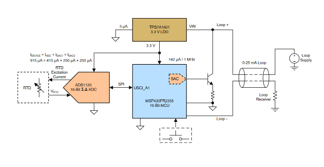
It uses an on-chip Smart Analog Combo (SAC) module in the MSP430FR2355 MCU to control the loop current so that a standalone DAC is no longer required. This design offers a 12-bit output resolution; output current resolution is 6 μA. The design incorporates reverse-polarity protection as well as IEC61000-4-2 and IEC61000-4-4 protection on the loop-power input, Figure 3.

This FAQ on the 20-mA current loop for industrial sensing and control has explained the basics of this widely used standard which is “ancient” when judged by the timescale of modern electronics. It also has explained why it is still widely used in new installations, how it has evolved and been adapted for the digital age, and how additional capabilities such as self-powered operation have allowed it to be even more useful and relevant.
References
- EEWorld Online, “Current sources and why we need them”
- EEWorld Online, “Options for current sensing, Part 1”
- EEWorld Online, “Options for current sensing, Part 2”
- Wikipedia, “Highway Addressable Remote Transducer Protocol”
- FieldComm Group, “HART – Digital Transformation for Analog Instruments”
- Analog Devices, “HART Communication Made Easy”
- Texas Instruments, “TIDM-01000 4- to 20-mA Loop-Powered RTD Temperature Transmitter Reference Design With MSP430 Smart Analog Combo”
- Maxim Integrated, “MAX1290 Ultra-Low-Power 4-20mA Sensor Transmitter”
- National Instruments, “Fundamentals, System Design, and Setup for the 4 to 20 mA Current Loop”
- PDH Center, “Understanding 4 to 20 mA Loops”
- Precision Digital Corp., “Back to Basics: The Fundamentals of 4-20 mA Current Loops”
- Precision Digital Corp., “Back to Basics: The Fundamentals of Loop-Powered Devices”


