
You’ve been given an “easy” assignment: get the low-rate data from a temperature sensor to a control computer located 100 feet (30 m) away, in an industrial setting. After much investigation and assessment, you choose a widely used standard called the 20-mA loop, which has been in use for over 50 years, rather than Wi-Fi, Bluetooth, ZigBee, wired Ethernet, or even wired RS-232/423. While others are mystified by the choice of this “ancient” standard, it actually makes a lot of sense.
This FAQ will explore the current loop for signal acquisition and control, and explain the rationale used here. It will look at how enhancements to the original loop concept have kept it a very viable option despite its age.
Q: At its simplest, what is this 20-mA loop?
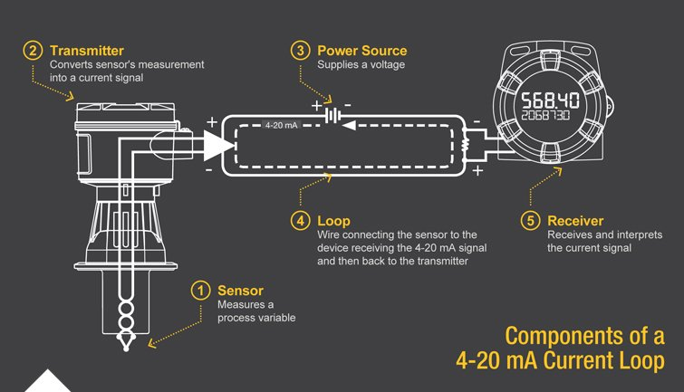
A: Sometimes called a 0-20 mA current loop or a 4-20 mA current loop, this wired interface standard is disarmingly simple: it uses an analog current of 4 mA to indicate the lowest end of the scale, and 20 mA for the highest, Figure 1. The signal from the sensor (often millivolts) is scaled to span from 4 to 20 mA, representing its smallest and largest output values, respectively. The current-loop signal was initially used in all-analog systems, even before digital control was envisioned, and it was used as electrical controls replaced pneumatic ones in industrial installations.
Q: Can this be used with digital signals, as well?
A: Yes, usually with 4 mA for a binary 0 and 20 mA for a binary 1. More on this is Part 2.
Q: Where is this 4-20 mA interface standard used?
A: It is used primarily in industrial settings where the signals from a sensor to a controller, and from a controller to an actuator, must travel long distances in a noisy, electrically hostile environment.
Q: Why use a current loop rather than a voltage-driven wired signal, such as RS-232, RS-423, RS-485, or other?
A: There are two reasons:
- First, as a low-impedance loop, the wire is inherently resistant to noise pickup. A voltage signal, on the other hand, would put voltage on high-impedance wire and so would be susceptible to noise as well as IR-voltage drop over long runs with thinner wires. Keep in mind that any current entering the loop must travel in a “circle” back to the source, so there is no opportunity for current loss or gain, by Kirchhoff’s Current Law (KCL), Figure 2. In practice, the loop supply may be a fixed DC voltage for convenience, typically between 12 and 30 V, but the internal electronics at the sourcing end converts this voltage source into a controlled current source.
- Second, the current loop has a major, natural self-diagnosing attribute: if the wire loop breaks anywhere – the most-common fault mode – the current drops to zero, which is easily and automatically detected by circuitry (and an alarm flag called “break detect can be set), and eventually locate.
Q: How is the current loop implemented for a sensor, and for an actuator?
A: Transducers divide into two major groups: sensors and actuators. For sensors, the signal-conditioning circuitry is called a transmitter. It contains a controllable current source which is designed to supply the 4 mA at the minimum sensor output value and 20 mA at the maximum, and be linearly proportional in between those endpoints. For actuators such as valves or motors, the control unit sends a 4-mA signal for minimum value setting or motor speed, and 20 mA for maximum position or speed, and again proportional in between. At the far end, a receiver translates the current into the appropriate drive voltage, current, and type for the actuator,
Q: Why not use Wi-Fi or another wireless standard, or even wired Ethernet or similar?
A: In addition to the two issues of inherent noise resistance and fault indication, the current loop has other virtues. It is inexpensive, easy to set up and debug, easy to troubleshoot, is reliable, and can handle long distances (even thousands of feet as long as the controlled current source have enough driving voltage to overcome voltage drop in the wires).
In contrast, the other standards are harder to set up and maintain, are susceptible to noise and hacking, and are costly. A wirelessly link in an industrial environment over a short distance is possible but often challenging; over a longer distance, it can become surprisingly complicated, and various levels of noise filtering, and data error-correction and redundancy needs to be included. All that adds up to considerable, cost, and risk for connecting to a simple temperature sensor or valve/motor controller.
Q: How is the current loop signal from a sensor transformed into a useful voltage for use by the controller?
A: It’s fairly easy: the current is passed through a resistor, and an op amp or other amplifier measures the voltage across the resistor. For various reasons, the industry has standardized on using a 250-ohm resistor, so 4 mA translates to a 1-V signal while 20 mA becomes a 5-V signal. One volt is large enough to be easily measured, and is higher than most noise levels, and 5 V is larger but still within the headroom and range of analog circuitry and any subsequent signal processing. At the same, time, the maximum I2R dissipation of the resistor is just 0.1 W, which is acceptable even in space-limited, warmer installations with limited cooling capacity.
Q: It seems like the 20-mA current loop may be stuck in the past, used only for legacy design, with no new support electronics. Is this the case?
A: Not at all: IC and instrumentation vendors are still releasing new products supporting this interface standard.
Part 2 of this FAQ will look at additional capabilities of the 20-mA loop and how the digital and low-power worlds have adapted it.
References
- EEWorld Online, “Current sources and why we need them”
- EEWorld Online, “Options for current sensing, Part 1”
- EEWorld Online, “Options for current sensing, Part 2”
- Wikipedia, “Highway Addressable Remote Transducer Protocol”
- FieldComm Group, “HART – Digital Transformation for Analog Instruments”
- Analog Devices, “HART Communication Made Easy”
- Texas Instruments, “TIDM-01000 4- to 20-mA Loop-Powered RTD Temperature Transmitter Reference Design With MSP430 Smart Analog Combo”
- Maxim Integrated, “MAX1290 Ultra-Low-Power 4-20mA Sensor Transmitter”
- National Instruments, “Fundamentals, System Design, and Setup for the 4 to 20 mA Current Loop”
- PDH Center, “Understanding 4 to 20 mA Loops”
- Precision Digital Corp., “Back to Basics: The Fundamentals of 4-20 mA Current Loops”
- Precision Digital Corp., “Back to Basics: The Fundamentals of Loop-Powered Devices”


