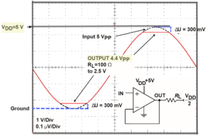
With respect to analog signals, a “rail” is a boundary that a signal has to work within. For a long time, operational amplifiers have required opposite but equal voltage supplies. If you see a dual-supply or dual-voltage op amp, it means that two supply voltages power the amplifier; the absolute supply voltage levels are the same, except one is negative and swings below 0 V, and the other supply voltage is positive and swings above 0 V. “Single-supply” op amps came later on and are more convenient in that only one voltage supply is needed to power them.
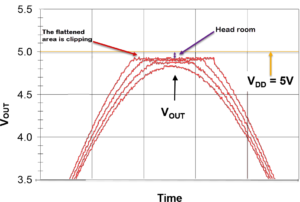
Rails refer to supply voltage levels. An upper rail on the voltage output of an op amp refers to the highest voltage level that it can reach, which is limited by the supply voltage powering the op amp. “Rail-to-rail” implies that the signal swings all the way to supply voltage levels on both the positive and negative rails. But does it? Not really. Only a frictionless system would be able to take in energy, act upon it to perform some work, and then have the output be at the same energy level that was put in. The term “rail-to-rail” is marketing speak for “darn close.” Some advertisements state that they go “beyond the rails,” but going beyond the rails usually means clipping the signal. The maximum peak-to-peak voltage output swing is one where the waveform is not clipped with reference to a specified level.

Some commonly used terms are rail-to-rail input/output (RRIO) and rail-to-rail output (RRO). If an op amp can drive RRO, it means you have a good dynamic range in which to work on the signal. A related term, head room, is a measure of how close the signal comes to the rails. The distance from the rail to the peak voltage output signal is the head room. Head room of 0.3 V with a 3.3 V supply voltage means that your signal can reach +/- 3.0 V without distortion (head room refers to both positive and negative supply rails). Head room increases as output current increases.

Let’s look at a hypothetical example. Any analog signal, measured in voltage levels, has a tight space to work in if the supply voltage is just +/-3.3 V (for a total output swing of 6.6 V). Let’s say the op amp is not RRO and the signal’s highest voltage level on the output of the op amp is 3.0 V. Now, noise is hard to avoid, so let’s be realistic and assume that noise is riding on the analog signal, adding or subtracting as much as +/-0.4 V to the true signal. (The true signal is the one that you worked out on paper or in a computer simulation in a neat, noise-free world.)
Therefore, with a supply voltage of 3.3 V, you lose 0.3 V of dynamic range because we don’t live in a frictionless world. Electrons lose energy as they drive through circuits to perform work, and energy is lost through heat and so forth. Now, assume you have set an alarm trigger to go off if the signal reaches 2.9 V. Your trigger may set when your analog output is actually just 2.5 V, because a +0.4 V peak voltage of noise gets added on top of the signal, which the trigger sees as 3.0 V coming out of the op amp. The system cannot differentiate noise from the signal, so it sees 2.5 V + 0.4 V = 2.9 V and lets the trigger go. On the other hand, the noise could cause a negative dip in the output, causing the trigger to not go off when intended (or possibly never), because at 2.9 V – 0.4 V, the signal is seen as reaching +2.5 V at most.
A RRO amplifier is supposed to give you almost the full range as bounded by the supply voltage (Vs). With a Vs of 6.6 V, the positive rail is +3.3 V, the negative rail is -3.3 V, and if the op amp is rail-to-rail, the output might actually be bounded at 3.25 V. Thus, the 0.4 V noise would still be there but less effective.
The above are only examples. You should look at the data sheet for the highest output voltage (VOH) and the lowest output voltage (VOL) of your RRO op amp to determine what you’re actually getting. Figure 2 below shows a section of the Analog Devices datasheet for the ADA4622; a single-supply RRO op amp. The ADA4622 has a single supply voltage of 30 V (but the op amp splits that 30 V into two rails to swing between: +15 V and -15 V). Note that the typical VOH is very close to the rail at 14.97 V, but the worst you should experience is +14.95 on the upper rail. The lower rail is at worst going to be -14.935. In other words, Vs -VOUT = VOH.

The term is a fast way to determine if you are working with as much head room as possible and looks good in the title of the datasheet. Don’t get hung up in the rails. For a deeper understanding of how RRO op amps get so close to the rails, see Microchip’s application note ADN009, “What does ‘Rail-to-rail’ Operation Really Mean?” by Bonnie Baker and Texas Instruments’ application report SLOA039A, “Application of Rail-to-rail Operational Amplifiers” by Andreas Hahn.
