Understanding how filters are characterized is the first step in choosing an appropriate topology with suitable specifications.
Mention “filters” to electrical engineers of the older persuasion, and you’ll likely see a look of nostalgia mixed with fear. Why so? Because “back in the day” a course on filter theory was mandatory for nearly all EE students. This course combined arcane math with some real circuits, various graphs and plots of presumed filter performance, and much more into a syllabus that was intense, scary, and forbidding, except for the small percentage of the students who loved it. For others, it was a rite of passage to go through and then stay away from, if possible.
But you can’t stay away from filters. Like so many things in life, filters are extremely important in circuit and system design. As the saying goes, “maybe you can’t live with them, but you certainly can’t live without them, either.” One – and often, many – filters are present in almost any circuit which handles power or processes a signal in some form. There’s no way around that reality.
What has changed is that most engineers no longer have to design and fabricate filters on their own or do so from “scratch.” While filters made of discrete components are still widely used, in many cases the filtering function is embedded within an IC or purchased as a “canned” off-the-shelf function. The specifics can be worked out even when using discrete components by entering needed performance parameters into one of the many available filter-design programs. Not only does this save design time and reduce frustration, but the technical demands on filters have increased significantly, and good designs are harder to work out, so a good application package can be a big help here.
This FAQ is NOT about filter design, details, equations, analysis, or theory. Instead, it will focus on understanding the many parameters which define a filter for a given application. There will be no math, not even basic equations, but there will be diagrams.
There is no filter choice that is perfect for all applications or even a single given. As with almost all engineering decisions and options, each filter solution presents tradeoffs and compromises in performance, practicality, size, power, cost, tolerance sensitivity, and other factors.
Q: What is a filter?
A: A filter is a linear two-port circuit-block which allows circuit energy (voltage, current, or RF power) to pass or be blocked, depending on the frequency of the energy. It’s that simple. (Some filters operate on signal magnitude rather than frequency – those non-linear analog filters are in a whole different class and are excluded here.) Optical filters use various thin films on substrates rather than optical circuits, so they, too, will not be covered here.
Q: Is a filter a frequency-domain or a time-domain construct?
A: It’s both, of course, since those two domains are equally valid representations of the same occurrence. Most filter discussions are done in the frequency domain, but sometimes it is necessary to go to the time domain as well.
Q: What defines a filter’s performance?
A: many factors do, but it all starts with a transfer function, the equation which describes the output with respect to the input. This transfer function is a polynomial of various levels of complexity.
Q: What are the basic classes of filters?
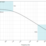
A: Despite all the filter complexities, it all comes down to just four categories, viewed in the frequency domain: low-pass, high-pass, band-pass, and band-stop (notch) (Figure 1). Nearly all filters are variations on these four categories. For the ideal filters shown – a concept which will be explained later – the passband is where the signal is allowed to pass, while the stopband is where it is severely attenuated.

Q: What are filters used for?
A: Almost everything. It’s impossible to list even a large fraction of their uses. A few of them are:
- reducing 50/60 Hz powerline noise on a non-power signal.
- conversely, “cleaning up” a 50/60 Hz signal by attenuating noise on the line.
- selecting/tuning a specific channel in the broader spectrum (can be wired or wireless).
- attenuating unwanted noise caused by power-supply switching action.
- eiminating out-of-band signals for anti-aliasing in sampled-data systems.
- minimizing externally sourced electromagnetic interference (EMI) that enters a system and affects operation, whether from random source (nearby industrial-motor brushes) or another radio transmitter.
The next part of this article continues by explaining filter basics.
Related EE World Content
- A scope-based technique for optimizing EMI input filters
- 5G RF filters need more innovation
- Filters offer ‘brick-wall’ performance to 7 GHz for semiconductor and IC testing
- Basics of audio filters
- What are switched capacitor filters, amplifiers and integrators?
- How to design modular DC-DC systems, Part 2: Filter Design
- RF/Microwave bandpass filter implementations, Part 1: Distributed filters
- RF/Microwave bandpass filter implementations, Part 2: Cavity and comb filters
- RF/Microwave bandpass filter implementations, Part 3: Microstrip, Coaxial, and helical filters
- Filters, Part 1: Analog, switched, and digital filters
- Filters, Part 2: SAW and BAW devices for RF
- 5 things you need to know about 5G filters
External References (note: Most of these are “equation-light” references)
- Student Circuit, “Electronic Filter”
- All About Circuits, “An Introduction to Filters”
- ElectronicFundablog, “Filters – Classification, Characteristics, Types, Applications & Advantages”
- Electrical Technology, “Types of Filters and Their Applications”
- Electronics Tutorials, “Passive Low Pass Filter”
- Wikipedia, “Electronic Filter”
- Wikipedia, “Low-pass filter”
- Wikipedia, “RC Time Constant”
- Thor Labs, “Relationship Between Rise Time and Bandwidth for a Low-Pass System”
- Georgia State University, “Filter Circuits”
- Wiki Lectures, “Time constant and filters”
- Coilcraft, “Filter LC responses”
- Swarthmore College, “Frequency Response and Active Filters”
- EL-PRO-CUS, “Tutorial on Different Types of Active Filters and Their Applications”
- Technobyte, “Filter Approximation and its types – Butterworth, Elliptic, and Chebyshev”
- Embedded Related, “First-Order Systems: The Happy Family”