Understanding how filters are characterized is the first step in choosing an appropriate topology with suitable specifications.
This part looks at the basics of filter characterization and parameters.
Q: What is an example of a very basic filter?
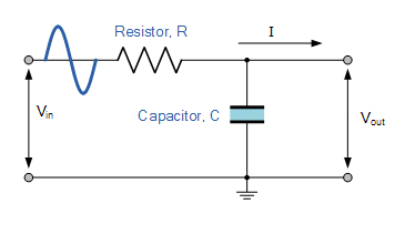
A: The most common analog filter is the single-stage low-pass RC filter (Figure 1). It is often used to keep higher-frequency noise out of a system.
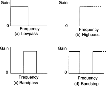
Q: What are the primary parameters which must be specified when designing or choosing a filter?
A: It usually starts with frequency and filter type (choosing among the four basic functions). For the low-pass and high-pass filters, it is the transition frequency from passband to stopband, or stopband to passband, respectively. For the passband and notch filters, it is the center frequency of the passband or notch.
Q: What else is used to characterize filters?
A: Bandwidth being the next most common consideration.
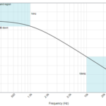
Q: How is it defined?
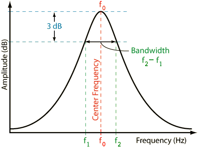
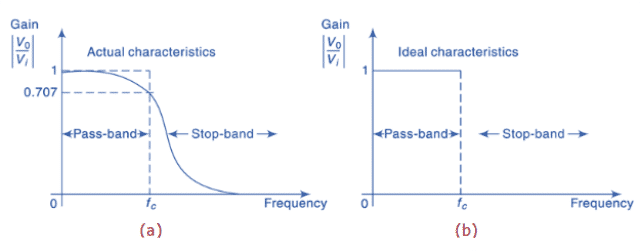
A: Usually, but not always, it is the frequency span where the filter response is 3-dB below its peak value (Figure 2). It is also the half-power point or where the voltage is 0.707 (1/√2) of its peak value.
Q: That’s it for bandwidth?
A: No, there’s more. Since 3-dB attenuation is only a modest amount (half-power), many applications need to define bandwidth at higher attenuation levels, such as 60 dB. This leads to a parameter called “roll-off” rate, characterized by how many dB per octave of frequency or dB per decade the attenuation increases.
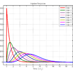
Q: How is the roll-off rate characterized?
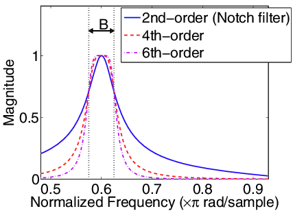
A: The rolloff rate is the rate of change of the output of the filter versus frequency. It is expressed as a loss per decade (a ten-times increase in frequency) or per octave (a two-time increase in frequency. The roll-off rate of the nth-order filter is 20 × n dB/decade or 6 × n dB/octave, where “n” is the order of the filter (Figure 3). A “sharp” multistage filter may have a roll-off of 20 dB/decade, while a less-sharp single-stage one will have just a 3-dB/decade value. The rolloff region of a filter is sometimes called its “skirt.”
Q: What is the passband and the stopband?
A: Passband is the band of frequencies of the input signal that passes through the filter with an attenuation of less than 3 dB attenuation, while stopband is a band of frequencies of the input signal that are blocked or more highly attenuated by the filter. (General convention is that amplitude at the stopband is 3 dB below the amplitude of the input.)
Q: What is cutoff or corner frequency?
A: The cutoff frequency or corner frequency is the transition zone between the passband and stopband. Again, this is where the output signal’s voltage is 70.7% of the input signal’s voltage, also known as “minus 3-dB frequency” because -3 dB represents half power.
Q: What’s an ideal filter look like?
A: An ideal filter, also referred to as a “brick-wall” filter, has an infinitely sharp transition between passband and stopband and no ripple in passband or stopband (Figure 4 and Figure 5). While such a filter does not exist in practice, designers can come closer and closer by adding more “orders” to the filter transfer function via additional filter stages. As always, though, there are real-world tradeoffs in cost, complexity, sensitivity to component tolerances and drifts, and other factors to evaluate as the filter order increases.
Q: What else characterizes a filter’s performance?
A: The answer depends on the filter type and the perspective of the user. In a band-pass or band-reject (notch) filter, there are two cutoff frequencies: the lower cutoff frequency (the lower frequency at which the output amplitude of the filter is “3 dB down”) and the upper cutoff frequency (the upper frequency where, again, the filter response Is 3 dB down). The center frequency is the frequency that is midway between the lower and upper cutoff frequencies, and the frequency range between the lower and upper cutoff frequencies is the bandwidth. Most filters are symmetrical around that center frequency, but some are not by design (although it’s tricky to design!).
Q: Is the attenuation consistent or “flat” in the passband and stopband?
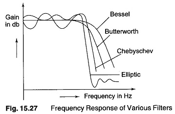
A: Generally not. Some filter a smooth variation, while others have what is called “ripple” in the bands. The ripple can be small, such as 0.25 dB or several dB. A filter with the lowest ripple is called maximally flat. The amount of ripple which can be tolerated is yet another parameter which is a function of the application. There are also considerations of passband versus stopband ripple: an elliptic filter (also known as a Cauer filter) has the sharpest roll-off (good) but also the highest ripple behavior (less good) in both the passband and the stopband (Figure 6).
Q: What are some other commonly used attributes?
A: There’s “critical frequency”, the frequency at which the response leaves the passband ripple, and “transition band”, the range of frequencies between the critical and cutoff frequencies. (The slope or steepness of the transition region is related to the number of poles in the transfer function of the response.)
Q: Finally, what is “Q”?
A: Q is the “quality factor.” For a bandpass or notch filter, Q represents the ratio between the center frequency and the 3-dB bandwidth; a higher-Q filter has a narrower, sharper response graph. Q is determined by both the filter design in theory and the real-world, non-ideal performance of its components.
The next part of this article looks at filters in the time domain and their phase-performance considerations.
Related EE World Content
- A scope-based technique for optimizing EMI input filters
- 5G RF filters need more innovation
- Filters offer ‘brick-wall’ performance to 7 GHz for semiconductor and IC testing
- Basics of audio filters
- What are switched capacitor filters, amplifiers and integrators?
- How to design modular DC-DC systems, Part 2: Filter Design
- RF/Microwave bandpass filter implementations, Part 1: Distributed filters
- RF/Microwave bandpass filter implementations, Part 2: Cavity and comb filters
- RF/Microwave bandpass filter implementations, Part 3: Microstrip, Coaxial, and helical filters
- Filters, Part 1: Analog, switched, and digital filters
- Filters, Part 2: SAW and BAW devices for RF
- 5 things you need to know about 5G filters
External References (note: Most of these are “equation-light” references)
- Student Circuit, “Electronic Filter”
- All About Circuits, “An Introduction to Filters”
- ElectronicFundablog, “Filters – Classification, Characteristics, Types, Applications & Advantages”
- Electrical Technology, “Types of Filters and Their Applications”
- Electronics Tutorials, “Passive Low Pass Filter”
- Wikipedia, “Electronic Filter”
- Wikipedia, “Low-pass filter”
- Wikipedia, “RC Time Constant”
- Thor Labs, “Relationship Between Rise Time and Bandwidth for a Low-Pass System”
- Georgia State University, “Filter Circuits”
- Wiki Lectures, “Time constant and filters”
- Coilcraft, “Filter LC responses”
- Swarthmore College, “Frequency Response and Active Filters”
- EL-PRO-CUS, “Tutorial on Different Types of Active Filters and Their Applications”
- Technobyte, “Filter Approximation and its types – Butterworth, Elliptic, and Chebyshev”
- Embedded Related, “First-Order Systems: The Happy Family”