• Skip to primary navigation
  • Skip to main content
  • Skip to primary sidebar
  • Skip to footer

Analog IC Tips

Analog IC Design, Products, Tools Layout

  • Products
    • Amplifiers
    • Clocks & Timing
    • Data Converters
    • EMI/RFI
    • Interface & Isolation
    • MEMS & Sensors
  • Applications
    • Audio
    • Automotive/Transportation
    • Industrial
    • IoT
    • Medical
    • Telecommunications
    • Wireless
  • Learn
    • eBooks / Tech Tips
    • FAQs
    • EE Learning Center
    • EE Training Days
    • Tech Toolboxes
    • Webinars & Digital Events
  • Resources
    • Design Guide Library
    • Digital Issues
    • Engineering Diversity & Inclusion
    • LEAP Awards
    • Podcasts
    • White Papers
  • Video
    • EE Videos
    • Teardown Videos
  • EE Forums
    • EDABoard.com
    • Electro-Tech-Online.com
  • Engineering Training Days
  • Advertise
  • Subscribe

The practical magical first-order analog filter: Part 1

August 27, 2021 By Bonnie Baker Leave a Comment

Finding the right analog filter to build a sensor circuit doesn’t have to be complicated. Understandably, the plethora of filter options can be overwhelming. Also, selecting a less-than-ideal filter may result in compromises, potentially increasing system cost, or affecting performance. To help simplify filter selection, this series of blogs explore key considerations when assessing your system’s analog filter needs and available devices. For this, we will start with the 1st order low-pass analog filter discussion.

1storder low-pass filter applications

A low-pass filter attenuates higher frequency signals above the three-decibel (3dB) corner frequency. In the frequency domain, the 1st order low-pass filter response at its output allows DC to low-frequency signals to transmit in the passband (Figure 1).

Figure 1. A 1st order, low-pass filter frequency response with an initial magnitude of 0 dB and a 3dB corner frequency at 1 kHz. (Image: Analog Devices)

Figure 1, from Analog Devices Analog Filter Wizard, represents the frequency response of a 1st order 1 kHz low-pass filter. With the diagram, the magnitude (y-axis) starts at 0 dB through the passband, and with increased frequency, starts to attenuate at 1 kHz (x-axis). At 1 kHz, the low-pass filter Magnitude is -3 dB. Beyond 1 kHz, the filter attenuation characteristic is -20 dB per frequency decade or -20 dB/decade. Note that at 10 kHz, the filter magnitude is -20 dB, and at 100 kHz, the filter magnitude is -40 dB.

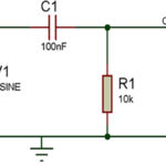
The circuit diagram for a 1st order filter can be passive with a resistor and capacitor or active with a resistor, capacitor, and operational amplifier (Figure 2).

Figure 2. The input of the passive low-pass filter (A) has R1 and C1 filter elements. Two active non-inverting low-pass filters (B) uses the same input structure with the following amplifier in a gain configuration. The active inverting low-pass filter (C) uses R2 and C1 in the feedback loop to implement the filter corner frequency. (Image: Bonnie Baker)

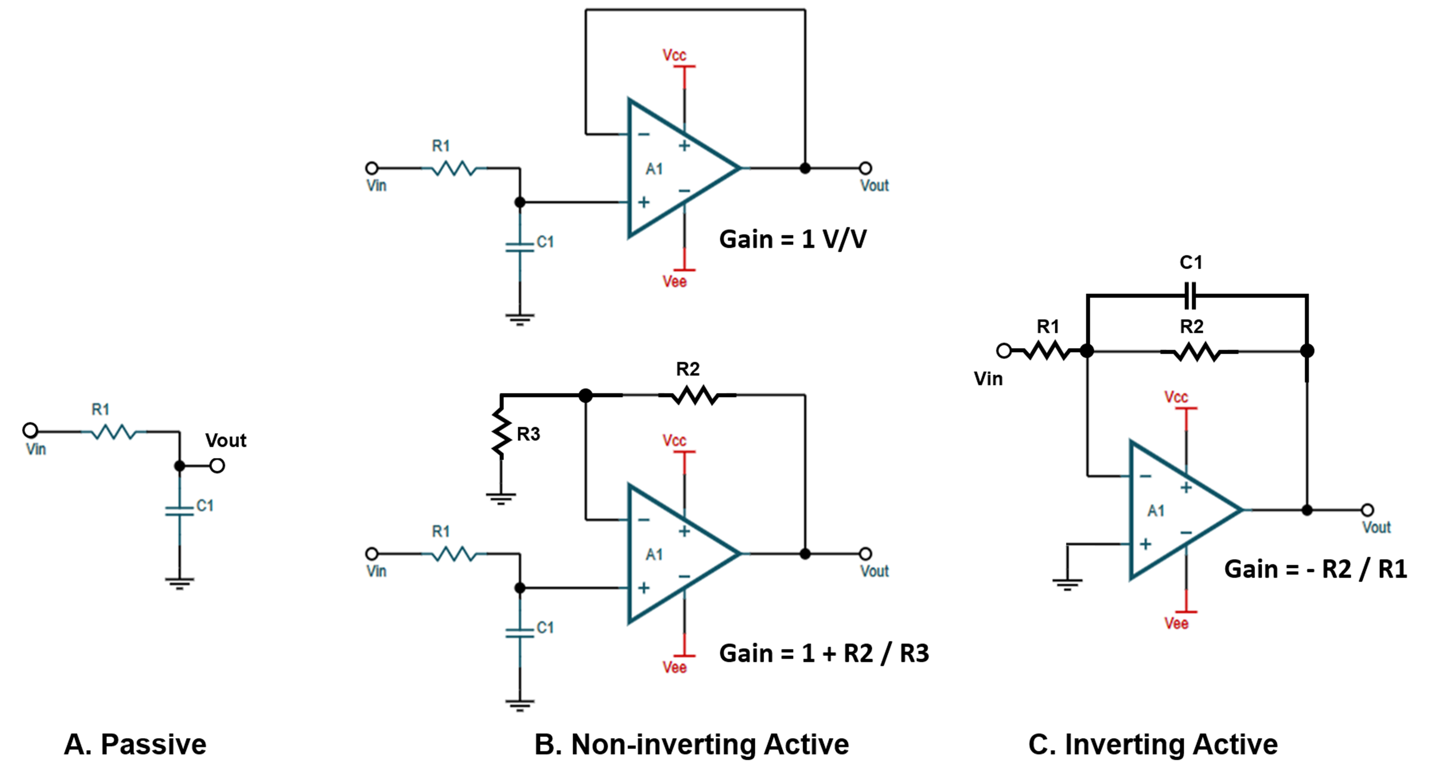
The transfer function Figure 2’s circuits are below.

transfer functions


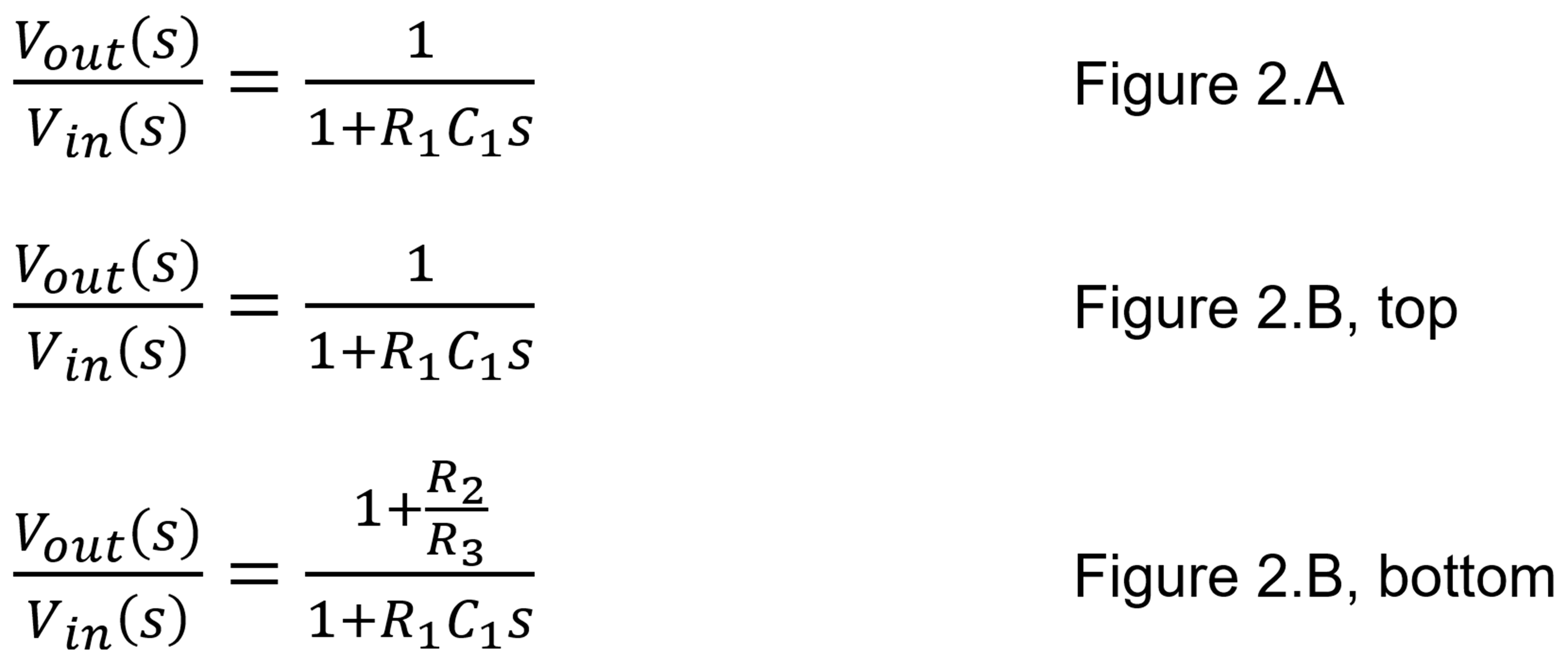
In all 1st order low-pass filters, the pole frequency equals:


In Figure 2, R1 and C1 equaling 159.15 kW and 1 mF, create a 1 kHz pole.

1st order low-pass filter applications

The 1st order low-pass filter can come in handy in numerous applications. The idea is to make sure that you are attenuating enough of the higher frequency noise in your application and to use the resistive and capacitive devices to your advantage.

The amplifier interface to a standard SAR analog-to-digital converters (ADC) utilizes a 1st order low-pass filter (Figure 3).

Figure 3. The placement of 1st order low-pass filter is very effective with a SAR-ADC converter. (Image: Bonnie Baker)

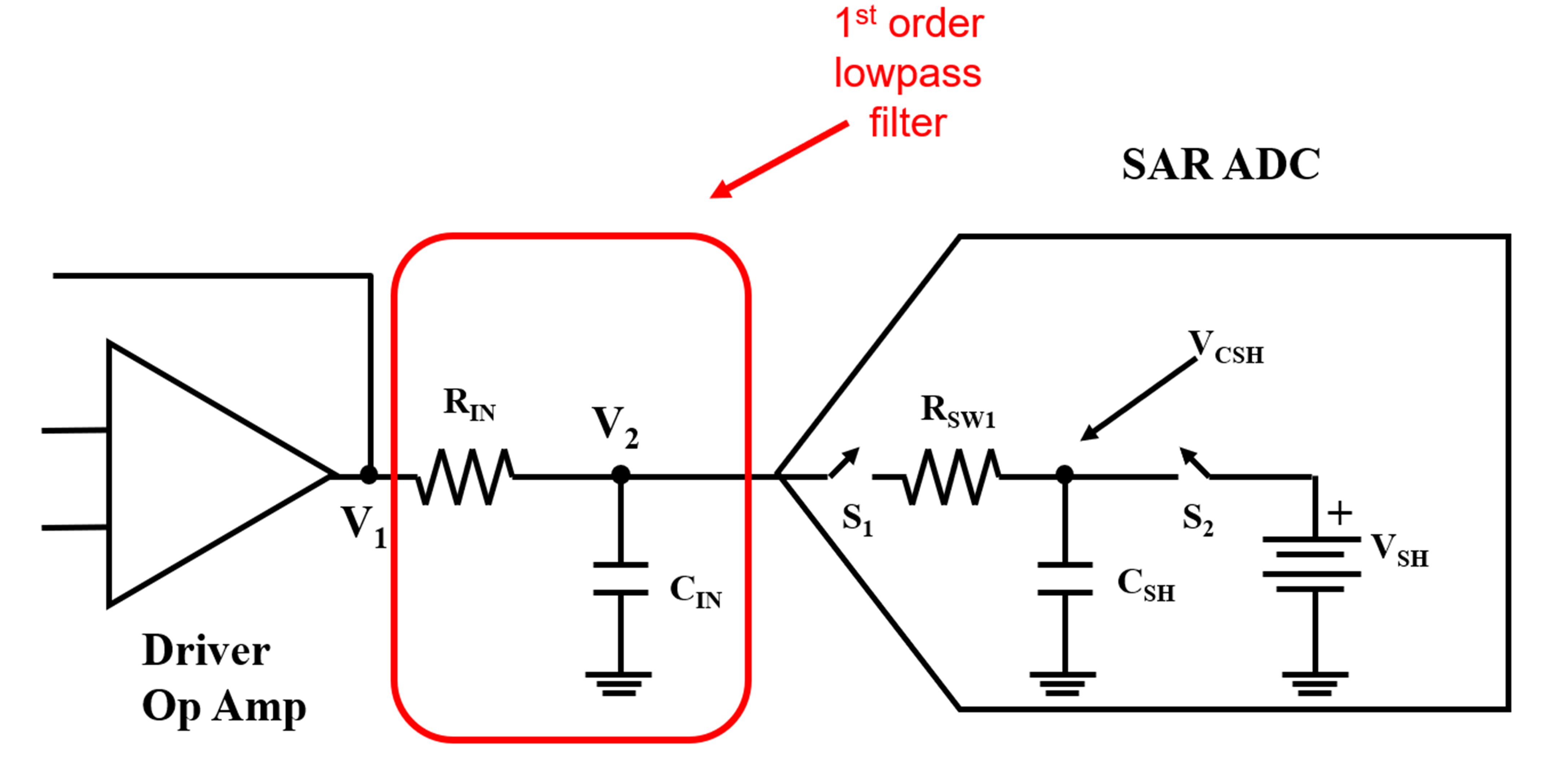
In Figure 3, the 1st order filter’s capacitor absorbs current spices from the SAR’s internal switch, S1. Proper selection of the RIN resistor brings stability to the driver amplifier’s response.

High-precision SAR-ADCs require a high-precision, buffered voltage reference. The 1st order filter’s design for a SAR-ADC voltage reference interface ensures the stability of the reference’s driver amplifier (Figure 4).

Figure 4. For High precision SAR-ADCs there is a buffered voltage reference with amplifier stability passive capacitive devices. (Image: Bonnie Baker)

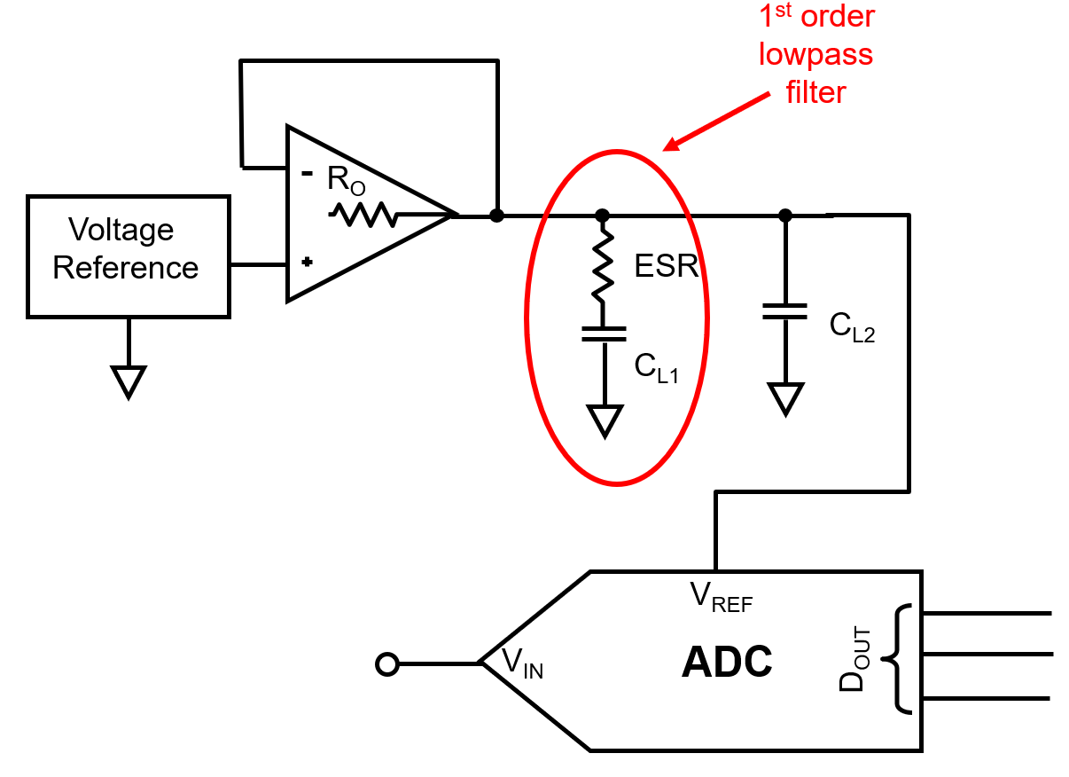
The resistive element of this 1st order filter is CL1‘s parasitic resistance (effective-series-resistance, ESR) stabilizes the voltage reference driver amplifier. The second capacitor, CL2, absorbs the ADC’s switching noise.

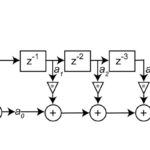
A delta-sigma ADC also requires a 1st order low-pass filter at its input. (Figure 5).

Figure 5. To obtain a high 24-bit resolution, a low-pass input filter to the ADC reduces high-frequency digital filter images. (Image: Bonnie Baker)

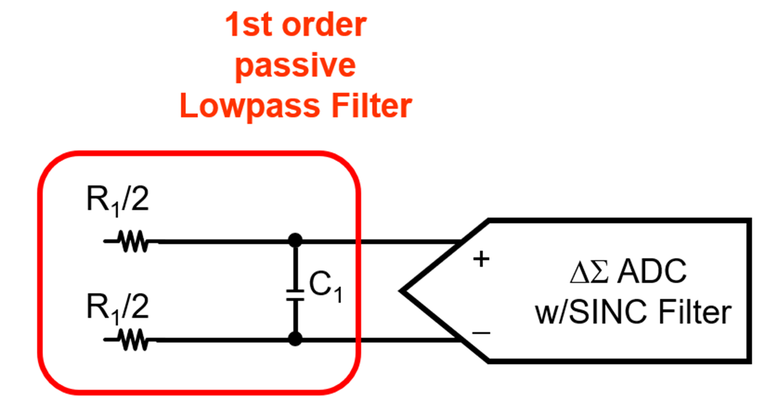
This passive filter removes high-frequency digital filter signal reflections.

Figure 6. (Image: Bonnie Baker)

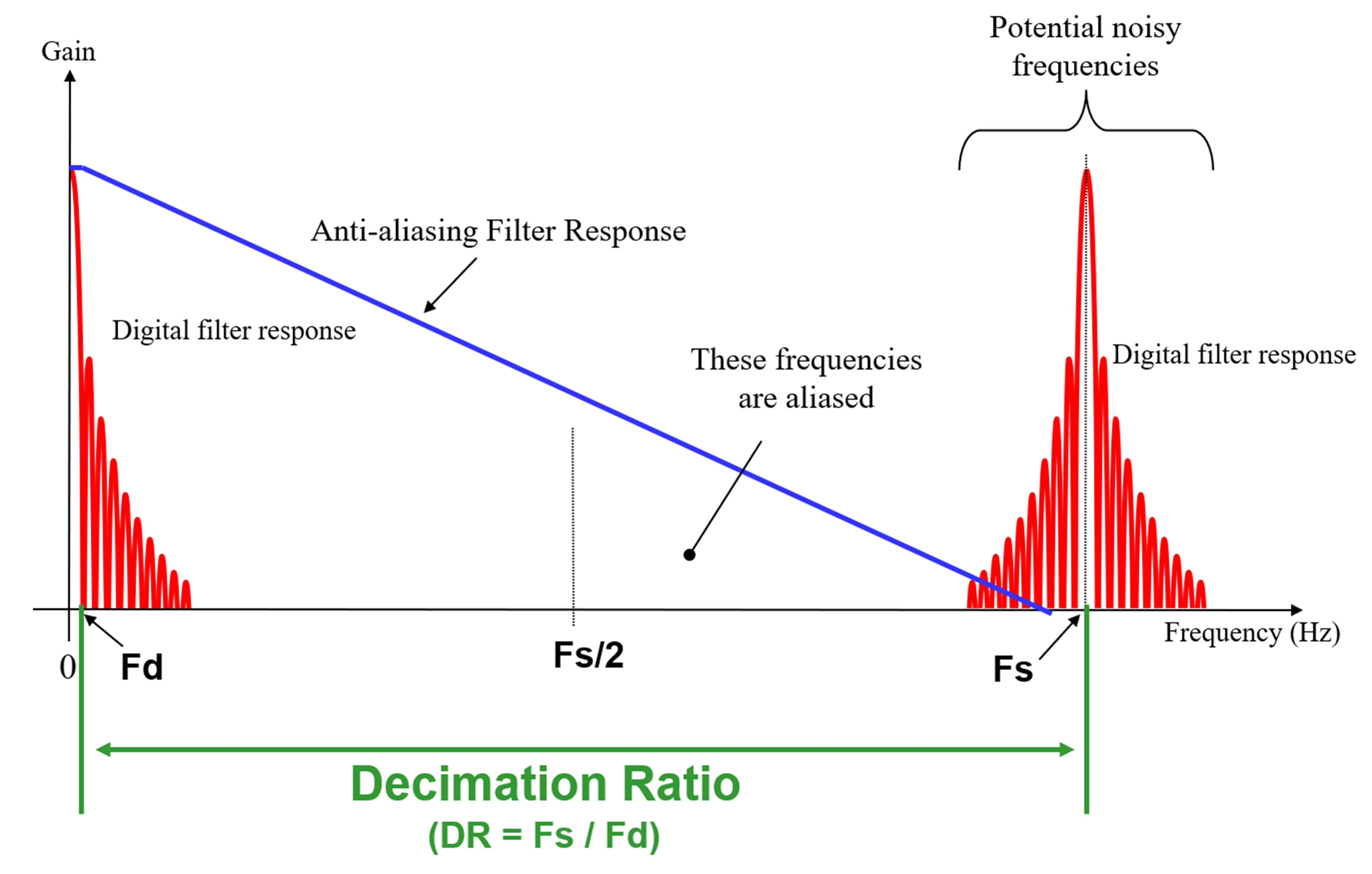
Since a delta-sigma converter is a sampling system, all noise and signals above ½ of the modulator’s sampling frequency aliases back (Figure 6). The digital filter attenuates the higher frequency noise except around the sampling frequency.

Usually, the amplitude of the noise and signal hovering around the sample rate is small, but noise is a reality, and it will be present in your circuit. To make this interesting, you have a high-resolution converter that shows the noise in its lower bits. This is why you’ll need a continuous-time filter in front of the delta-sigma converter.

In Figure 6, the lowest value for your analog filter, corner frequency, should be Fd. Fortunately, the required strength of this filter is low, and a simple 1st order low-pass filter is usually good enough.

Do I need a high-pass filter in my circuit instead?

The 1st order low-pass filter is helpful for a multitude of applications. However, there are instances where your system may require a high-pass filter. Read on to Part 2 of this blog filter series.


Filter Design Tools
“Analog Filter Wizard”, Analog Devices
“Filter Design Tool”, Texas Instruments

You may also like:

  • bandpass filters
    An overview of filters and their parameters, Part 1: Context
  • sound waves
    Audio filters: Understanding sound waves – Part 1

  • Basics of audio filters

  • Filters, Part 1: Analog, switched, and digital filters
  • RF/Microwave bandpass filter
    RF/Microwave bandpass filter implementations, Part 1: Distributed filters

Filed Under: Analog ICs, FAQ, Featured, filters Tagged With: FAQ

Reader Interactions

Leave a Reply Cancel reply

You must be logged in to post a comment.

Primary Sidebar

Featured Contributions

High-Performance GPUs Are Located in a Variety of Environments, including Data Center Racks.

AI’s demand for faster, more reliable IC testing

Design a circuit for ultra-low power sensor applications

Active baluns bridge the microwave and digital worlds

Managing design complexity and global collaboration with IP-centric design

PCB design best practices for ECAD/MCAD collaboration

More Featured Contributions

EE TECH TOOLBOX

“ee
Tech Toolbox: Power Electronics
Our latest eBook compiles essential technical articles covering freewheeling diodes, snubber circuits, coreless transformers in solid-state isolators, PWM current source converters, hot-swap implementation, inrush current analysis, and inverter switching strategies for battery longevity.

EE LEARNING CENTER

EE Learning Center
“analog
EXPAND YOUR KNOWLEDGE AND STAY CONNECTED
Get the latest info on technologies, tools and strategies for EE professionals.

EE ENGINEERING TRAINING DAYS

engineering

RSS Current EDABoard.com discussions

  • Is it possible to achieve this in Comparator?
  • Pliers for eletctronics repairs
  • Help with rs232 and can
  • Thermaltake psu TR2600L2NC
  • Question power soldering iron damage pcb and smd components

RSS Current Electro-Tech-Online.com Discussions

  • Raise your hand if your car had one of these:
  • MCS-51 Development Ecosystem
  • ESP32 Sub Forum
  • Please could you advise me on this circuit for car OBD2
  • Mitsubishi projection lamp
“bills

Footer

Analog IC Tips

EE WORLD ONLINE NETWORK

  • 5G Technology World
  • EE World Online
  • Engineers Garage
  • Battery Power Tips
  • Connector Tips
  • EDA Board Forums
  • Electro Tech Online Forums
  • EV Engineering
  • Microcontroller Tips
  • Power Electronic Tips
  • Sensor Tips
  • Test and Measurement Tips

ANALOG IC TIPS

  • Subscribe to our newsletter
  • Advertise with us
  • Contact us
  • About us

Copyright © 2026 · WTWH Media LLC and its licensors. All rights reserved.
The material on this site may not be reproduced, distributed, transmitted, cached or otherwise used, except with the prior written permission of WTWH Media.

Privacy Policy