Peer-to-peer, engineer-to-engineer questions and answers from the EDABoard.com engineering community around analog ICs and analog design. Click the “Read more” link and follow the entire conversation and maybe add your two cents by logging in to EDAboard.com.
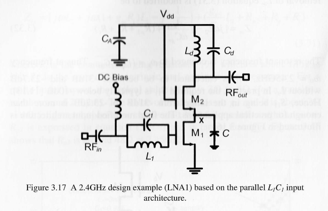
LNA circuit not working – I am trying to simulate an LNA circuit from the book “Design of CMOS RF Integrated Circuits and Systems.” However, it is still not working. Any help? Read more
 BJT V(ce) ON in common emitter mode – For an FMMT491A BJT with 2.7mA flowing into its base and set up in common emitter mode….is there any set of circumstances (temperature, i(ce) etc etc) which might ever result in its Vce(ON) voltage ever being greater than 0.5v? Read more
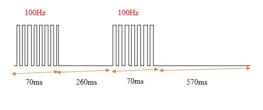
Square wave generation without microcontroller – I need a circuit that when a push-button is pressed then below square wave is generated four times. Do you have any idea to generate it without using a microcontroller and as simple as possible? Read more
Driving 140x 3W LEDs – This is a question about driving 140x LEDs which are rated from 3.2 to 3.6v and up to 700mA current (link for them here).
My design: I was thinking of using 24v to power 7x in series bringing the voltage down to 3.43v on each LED, and I think this is fine.
My application: This is a dual-sided PCB exposure box complete with a vacuum. So there will be 70 LEDs on each side. And I might switch on the bottom, the top or both at any time. Also based on assumption and on other projects I found, with that much power, it might take a maximum of 30 seconds to expose a full board. Is it correct that I will need 45.5AMP per side to drive 70x @ 650mA? I mean the math is correct but is there a better way to drive an LED? With regards to limiting the current, I am only familiar with putting a resistor in series… is there a better way? Read more
Circuit design help analog to potentiometer – Looking for help to build a circuit to convert analog input to potentiometer output. I am sending an analog signal 0-10vdc via a PLC card. I need to send out a 0-6.2vdc signal through a potentiometer. The reason being, the device (Lincoln welder) is currently being tuned with a potentiometer and has a built-in safety circuit. Read more
RF power amplifier design – In power amplifier design, how do you properly determine the biasing point of different classes such as Class AB, Class C, and so on? How do you do it through simulation using ADS? Read more
Separating supplies on PCB – have made my first FPGA design. I’m using a MAX10 board and an extension on which
I have set a DAC (MAX5875). For the moment, all my design does is generating a sine wave from an array (everything
is explained in the FPGA section). Now what happens is that the SN ratio is quite poor. I get around 70 dB. As the DAC is 16 bit, it’s 96 dB on paper, and according to the datasheet, it should be greater than 80 dB SFRD. So maybe it’s the proper time to design a new PCB. What I did (it’s my first DAC hardware) is putting all grounds together, all power lines together (of course the 1.8 and 3.3 are separated). Read more
What does “great linearity” means for a ring oscillator? – I just want to ask the significance or meaning of the phrase “good linearity” or “great linearity” as an advantage for the design of a ring oscillator. I am reading a paper about a bootstrapped ring oscillator and it says that “the proposed ring oscillator provides great linearity while the ring oscillator is controlled by power supply regulation.” What does it mean? Read more
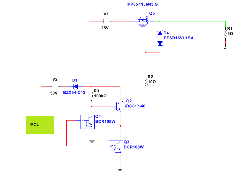
NMOSFET on high side? – I need to place an NMOSFET ON high side and control it with PWM approx. 400Hz. Q5 switch 25V to about 😯 ohm load. Read more
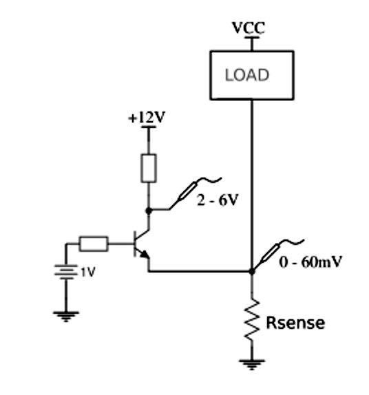
Single supply low-side shunt amplifier – I have a 250A/60mV shunt to monitor a power inverter operation. The shunt is located on the low-side (that’s it, the inverter ground is floating – max 60mV). As I only have a single supply available (+12VDC, the inverter housekeeping supply), is there any amp/opamp (or any other discrete method) available to amplify (x100) that small ground-referenced signal? As far as I have read, all INA instrumental opamps need a negative supply (but I must admit I have filtered my search on this further condition: I need a through-hole package or a discrete BJT/MOS solution). Read more