Peer-to-peer, engineer-to-engineer questions and answers from the EDABoard.com engineering community around analog ICs and analog design. Click the “Read more” link and follow the entire conversation and maybe add your two cents by logging in to EDAboard.com.
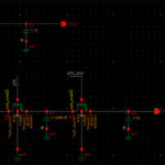
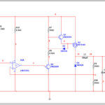
4-20mA current loop with common ground – I have this schematic for a 4-20mA current loop transmitter. My understanding is that the op-amp in my circuit compares its feedback from R4 with its input and adjusts its output so that the input voltage is equal to the voltage at R4. Then the Ohm’s law takes care that exactly 4-20mA would flow when the input is 1-5V. I need to transform the circuit in such way, so that the loop (“4-20MA_OUT” in my circuit) shares the ground (V-) instead of (V+), but can’t think of a way for the described comparison to work because one does not know the resistance of the loop. Read more
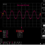
Hartley VCO for radio frequencies – Some time ago, I designed simple Hartley tunable oscillator working in the range 21-23 GHz band. How big was my surprise when during measurements I observed additional products in the frequency spectrum. It looks like the effect of mixing two signals (like in modulation process). Now I’m wondering what it is the cause of such behavior and I don’t have any practical idea what is going on. Below is the measured spectrum with frequencies marked. Read mor

Butterworth transfer function transformation – I have derived a 6th order Butterworth bandpass filter transfer function with center frequency of 2 MHz and two cutoff frequencies at 1MHz and 3MHz, I am now trying to implement the filter using two Thomas gm c architecture. I am trying to implement the attached tow Thomas circuit also using Vo2 and Vi2 as they are the ones that could correspond to my transfer function with 3 cascaded stages to reach the 6th order. Read more

OTA-C balanced cascode IC design – I am designing a balanced OTA with cascode output stage. I am using a Vdd of 1.2 maximum. What transistors dimensions and V for the two cascodes should I use in such circuit to bias the whole circuit? Read more


Circuit problem. Not getting 5 Volt on 7805 output – I am developing a circuit to have power and communication on the same wire. So, I thought about a digital signal that would vary from 5 Volt to 8 Volt. This way I am able to send signals to another processor and at the same time power that processor. All working good with the second processor. However, when the processor is generating the signal the 7805 output is not 5 Volt as it should. The output is around 5,7 Volts. Read more


My 5v to 7v level shifter, shifts 1.5v to 10v – I made a homebrew level shifter. In the LTSpice simulation it looks ok, but in reality it looks completely different. I wanted it to shift 5v to 7v, but first of all it pulls input down 1.5v and output becomes 10v, even though I only have 7v supply. Read more


Question on CMOS hysteresis comparator design – I’m designing a conventional CMOS hysteresis comparator. I noticed that the hysteresis level is changing according to the input frequency to trigger the output. Is it the hysteresis threshold level to change according to the incoming input signal frequency or should the threshold level not be changed. Read more
DC to AC converter 12V to +/-175V (40W) – I am currently trying to simulate/design a power converter that takes in 12V and outputs +175V and -175V AC sinusoidal output (delivering a maximum power to the load of ~40W a little less than this) Can anyone suggest a good topology that I should use for this any recommendations are warmly welcome I just need a starting point to work from. Read more
XOR output problem in HSPICE – I am using HSPICE to simulate 2-input xor gate, but for some reason the output is not as neat as I expected. Read more
Finding application for my voltage reference – My voltage reference circuit with 0.5V Vdd is designed to have a Vref of 0.3V. Designing this part is already done and is simulated using a capacitance load. What I need is a block that needs a 0.3V vref that operates in 0.5V Vdd. Read more