Peer-to-peer, engineer-to-engineer questions and answers from the EDABoard.com engineering community around analog ICs and analog design. Click the “Read more” link and follow the entire conversation and maybe add your two cents by logging in to EDAboard.com.
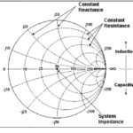
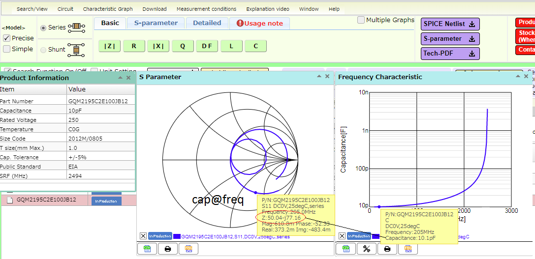
Calculate capacitance value from Smith Chart – How do I convert 50.04-j77.16 on a 50 Ohm Smith Chart to a capacitance value of 10.1pF? I am using GQM2195C2E100JB12. Read more
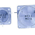
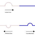
Passing both DC and pulses through a toroid – Suppose I have a toroidal core and I wind one turn of wire through it as my primary. My secondary is also one turn through this core. For the next description, assume no core saturation at any point. Now, suppose I pass DC 5v through the primary wire from left to right (this is just a representation to indicate the DC polarity to you). Nothing will be output on the secondary as a transformer will not work at DC. Now suppose I wind a second primary with one turn at the same phase as the first primary. If I feed a 5V rising edge to this second primary in the same direction as that of the DC, will this rising edge present at the secondary? Will this be 5v or 10v at the secondary? Read more
Question about RF power meter – I want to build a new EMF meter but EMF meters are limited they can work around 60 Hz, they can detect a wider range but still not enough for me, so I wanted to change my direction and build a power meter for all range detection. Which diode is good for all bands or which kind of circuit? Read more
Microwave power combiner/divider – I have simulated a two-way power combiner, two inputs port1 and port 2 are excited by two excitations with the same amplitude and combined in outport port3, but the results of s21 and s31 have a positive value (+ 2dB). My question is, can you have a positive value for s21 and s31 in dB? Read more
Ultrasonic transducer driver – I am new in this area in the analog domain. I have a piezo ceramic ultrasonic transducer for a humidifier. Specs:
Voltage: 5-12V
Res. Freq: 1,7 MHz
Res. Impedance: <2″”> I dont know what is this…
Coupling factor> 52%
Static capacitance: 1800pF
I want to make a driver for this transducer as simple as possible. Do you have any idea? Read more
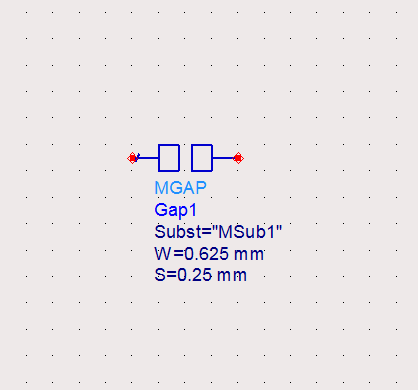
Microstrip to layout in ADS for power amplifier design – Can the microstrip gap (Mgap) used as a replacement for lumped components and transistor when we want to convert the schematic to layout? Attached is the Mgap in the schematic window. Read more
Generation of 4-phase shifted clock signals – How could we generate a phase-shifted signal clock signal (90,180, 270) with just basic components? Read more
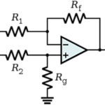
Closed-loop stable for negative phase margin? – Consider the following T(s)=1/(1+G(s))
Let G=K(s+1)^2/s^3. Let’s define wc=unity gain frequency & w180= -180 crossing frequency.
If K=10, we see that w180=1 but Gain(w180)=26dB. The GM is negative but if we look at poles of T(s) or Nyquist, it is stable!
This means that you can be stable even with negative GM!
But if K=0.25, we see that wc=0.725 and the phase(wc)=-198deg. The PM is -18deg as we are -18deg pass -180deg. And indeed we see that the closed-loop is unstable (poles of T(s) are RHP & Nyquist unstable). This leads me to wonder, is it possible to be stable if we have a negative PM with a different example? Read more
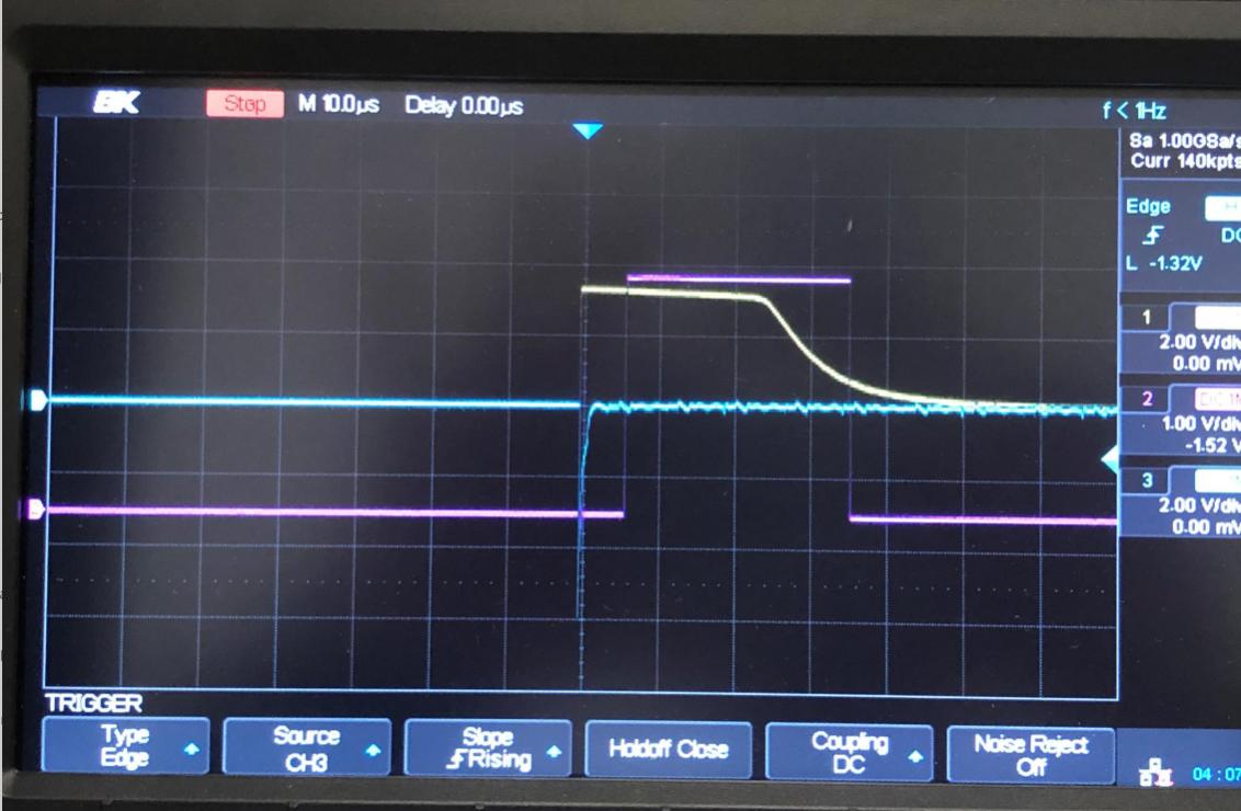
Photocoupler saturation? – There is a photocoupler (LTV-817) that I am using that is seeing a power glitch (~1 microsecond) and it seems to take a long time for the photocoupler to recover (~35 microseconds). The blue trace is the power glitch that I am seeing and the yellow trace is the “output” of the photocoupler. I was wondering if anyone had ideas on reducing the response time of the photocoupler (the yellow trace). At the output (yellow trace) what is happening? Read more