Audio electronics is a sector that refers to the circuit design that converts sound into electrical signals or electrical signals back into sound. Together, several circuits form an audio system.
An audio system has several functions and, typically, can:
- Receive audio signals (via a microphone)
- Record and save audio
- Transmit audio (through wired or wireless communication channels)
- Reproduce audio signals (via speakers)
The audio circuits are what perform the signal processing for the sound in the form of electrical signals. These circuits can also manipulate the electrical (audio) signals, such as through filtering, mixing, amplifying, or reproducing sound from the signals. Such processes are performed by different circuits or devices.
In this series, we’ll design three audio circuits as follows:
1. Audio crossover
2. Audio equalizer
3. Audio mixer
The audio crossover and equalizer are two different types of audio filters, which are one of the basic building blocks of an audio system.
Typical audio system

Before discussing the building blocks of an audio system, it’s important to understand the physics behind the sound. After all, the circuits designed for this project technically manipulate electrical signals to represent the audio.
Sound as waves
A sound is a form of energy, much like heat, light, and electricity are forms of energy. Sounds are produced, propagated, and detected as vibrations. As such, it follows that for the production of sound waves, a source is required to produce the vibration. Once produced, a vibration will disrupt any particles that are present in the surrounding environment — and these particles further disrupt any others that are nearby.
It might be easier to visualize these vibrations as a wave. An analog wave is produced by the compression and rarefaction of the particles. Technically, it’s this compression and rarefaction that creates a pressure wave, which is the sound. In other words, a sound is a pressure wave that’s characterized by the properties of a waveform-like amplitude, frequency, and time period.
Sound as a pressure wave

A sense of hearing is the ability to detect and recognize sound waves. The perception of sound by humans and animals is determined by the range of frequencies to which they’re attuned to. Every living creature has a different sound perception. For example, humans can hear sound frequencies in the range of 20 Hz to 20 kHz.
Sound pressure level
The physical properties of sound are quantified by a sound pressure level. It’s the measure of sound pressure in reference to the minimum level that humans can hear. Sound pressure is expressed as micropascals (µPa) or pascal (Pa), whereas the sound pressure level is expressed as decibels (dB).
Sound pressure
Sound pressure is the force (in Newton) on a surface area (m2) perpendicular to the direction of the sound. The unit of sound pressure is N/m2 or Pa (pascal). The lowest sound pressure audible by humans is 20 µPa and the maximum sound pressure perceivable by humans (which is also referred to as the pain threshold) is 20 Pa.
The sound pressure level is generally expressed in Db and is calculated as follows:
Lp = 10log(P2/P2ref)
Where…
Lp= sound pressure level
P = sound pressure (Pa)
Pref = reference sound pressure, 20 micro Pa
The reception of sound waves by human ears

Characteristics of a sound wave
A sound wave has three basic properties:
1. Pitch
2. Loudness
3. Tone
1. Pitch
The pitch is the individual perception of sound, which cannot be measured by any mathematical equation. Rather, it’s determined by how fast a sound wave is causing air particles to vibrate. It’s expressed as the frequency of a sound wave and represented by the compression and rarefaction of air particles. So, the frequency of a pressure wave physically represents how fast the compression and rarefaction of these particles are happening.
Although a pitch is typically described by the frequency of a specific sound wave, it’s not directly related to the frequency. The frequency is simply the physical property of the audio vibration that’s used to figure out the pitch of a sound.
The frequency of a wave can be determined by this equation:
Frequency = 1/Time
Frequency and the time period of a wave have an inverse relationship. For instance, as the time period goes up, the frequency goes down and vice versa.
This means the frequency of the sound wave indirectly expresses its pitch. Frequency is the number of waves in a given time period. The period can be one second, a minute, or an hour.
The standard (ISI) unit of frequency is Hertz (Hz). The Hertz is defined as the number of cycles per second. If there are 50 cycles in one second, for example, the frequency is 50 Hz.
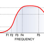
As human can hear sounds from 20 Hz to 20 kHz, this frequency spectrum is divided into different frequency bands:
- Sub-bass: 20 to 60 Hz
- Bass: 60 to 250 Hz
- Low mid-range: 250 to 500 Hz
- Mid-range: 500 to 2 kHz
- Upper mid-range: 2 to 4 kHz
- Presence: 4 to 6 kHz
- Brilliance: 6 to 20 kHz
A high-frequency wave has a higher pitch and a low-frequency wave has a lower pitch. Consider the sound of birds chirping (high pitch) compared to the sound of a dog barking (low pitch).
The sound frequency of a pitch

2. Loudness
Loudness is the auditory sensation that refers to the order of a sound wave from low to loud. Loudness is the property of the sound waves and it’s related to its amplitude. The higher is the amplitude, the louder the sound and vice-versa.
The amplitude of a sound wave is set by the vibration of the source. The source transfers the energy to a medium through vibration. A greater energetic vibration generates a larger amplitude.
Loudness represented by the amplitude of a sound wave

For humans, the loudness of a sound also depends on the sensitivity of their ears. As humans are sensitive to certain frequencies, loudness depends on the sound wave amplitude and the frequency within a perceived audio perception range.
The energy of a sound wave is proportional to the square of the amplitude. So, the greater the amplitude, the louder the sound and the more energy it carries.
Depiction of loudness based on the amplitudes of sound waves

3. Quality
A pure tone is the sound generated by only one frequency. In a sound wave, there are various tones or notes of frequency but the fundamental note (fo) has the highest amplitude so it can be heard easily. The fundamental note is the frequency at which an entire wave vibrates.
Frequency notes, which are a perfect integer multiple of a fundamental note, are called overtones or harmonics. The sound wave is a combination of fundamental notes and harmonics.
The presence of overtones or harmonics distorts a sound and its perception, and this is referred to as harmonics distortion. The fundamental note and the harmonics have different amplitudes and energy levels. The lower the amplitude of harmonics, and the lower the energy of all the harmonics combined, the greater is the quality of the sound.
Therefore, the amplitude or energy of the harmonics frequencies — such as 2fo, 3fo, 4fo, etc. — compared to the energy of the fundamental frequency, determines the quality of the sound wave.
In the next tutorial, we cover acoustic waves, which are a type of sound wave.