
by Kathleen Fasenfest, Senior Electrical Engineer, Antenna Products, TE Connectivity (TE) Aerospace Defense & Marine
Thanks to improved materials and novel processing, antennas today can be lighter, smaller and easier to make than their predecessors.
Antennas often don’t look the way they used to. The expanding consumer wireless industry has fueled rapid advances in injection molding and selective metallization technologies. Wireless antennas have swiftly evolved from printed circuit board and stamped metal designs to molded parts metallized with conductive inks. The high-volume manufacture of wireless antennas has quickly matured these technologies for the consumer market.
Several industries can benefit from this technological maturity. Injection molding of composites as well as processes for selective metallization offer paths for creating compact 3D antenna geometries, saving space and weight, minimizing part count, and even reducing aerodynamic drag for flight and automotive applications. Such 3D antenna designs can be mechanically robust and can withstand harsh environments.
However, some consumer-grade technology doesn’t work well in the harsh environments associated with such areas as aerospace and defense. Here, antenna materials must withstand vibration, mechanical shock, temperature and weather extremes, sometimes for decades. And low-loss metallization and substrates are needed because high-performance applications must minimize termal losses that boost heat and degrade antenna sensitivity.
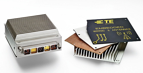
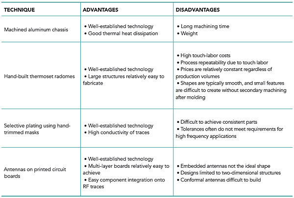
Structurally, antennas for super-tough settings often make use of machined aluminum parts and thermoset radomes. These fabrication methods are effective but costly. Machined aluminum parts are typically heavier than plastics and require more fabrication time. Plating is commonly used to selectively metallize surfaces. This plating typically involves hand-trimmed masks. The masks make it difficult to maintain the tight tolerances necessary for high-frequency applications. Similarly, thermoset radomes not only have a high labor content, but often need secondary machining to realize small features.
Antenna elements are commonly etched onto printed circuit boards (PCBs). PCB antennas allow easy fabrication through proven processes and sometimes can be integrated on the same board with matching circuits and other components. The main drawback is that these antennas are limited to 2D structures. Two-dimensional antennas may not efficiently use all the available space within an enclosure, and therefore, not provide optimal gain and bandwidth.
Recent advances in materials and fabrication technologies now make possible improved antenna designs that are smaller and weigh less, have high integration and are less expensive. Key innovations influencing next-generation antenna designs include composite materials and selective metallization processes. The resulting 3D antennas are mechanically robust and can withstand harsh environmental conditions. And they don’t bust the budget.
New generation composite materials offer two main benefits. They can be tailored to specific applications by careful selection of fillers; and they are injection moldable. Molding can create intricate and precise shapes with high repeatability.
Fillers are the secret sauce that make custom properties possible. Some useful fillers include carbon fibers, glass fibers, hollow microspheres, graphene, carbon nanotubes and foaming agents. Several critical antenna properties can be adjusted by careful application of fillers:
Dielectric Properties. Glass fibers boost the dielectric constant of most composites, reducing antenna size when these composites serve as substrates. Composite materials can also be engineered to provide “designer” dielectric constants through the addition of various filling materials, such as hollow glass microspheres, conductive particles or foaming agents.
Loss Tangent. A high loss tangent offers absorptive properties. Control of the loss tangent lets designers tailor RF absorption. Conductive-fiber fillers can absorb energy radiated in unwanted directions. This can raise antenna gain in a desired direction by cutting interference. The same direction-specific absorption can be used to shield electronics near antennas.
Lighter Weight. Conductive composites typically weigh 30 to 40% less than aluminum parts. Carbon fiber composites may also be sturdier than aluminum counterparts because they are not easily dented or deformed and won’t corrode.
High Conductivity. Carbon-fiber composites are addressing the need for lightweight, economical, mass-produced, electrically conductive parts to fabricate ground planes or EMI shields. For antenna applications, uses of carbon fiber composites range from ground planes to enclosures.
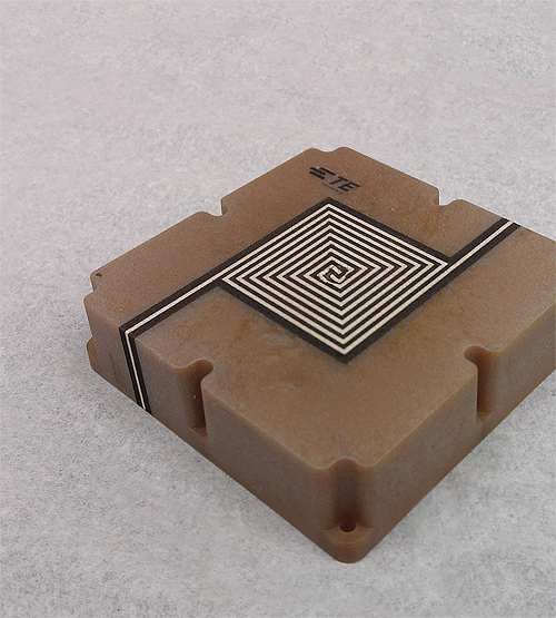
Newer metallization processes use several techniques to get costs out and improve performance. Key processes here include laser direct structuring (LDS) and conductive coatings. Both are selective metallization processes that can repeatedly make traces and fine structures as small as 100 μm. They are suitable for creating 3D antennas and traces on molded parts.
LDS is a three-step process. First, the substrate is molded in a standard thermoplastic molding process. Next, a laser etches the part to expose a specialized plating additive in the polymer resin. Finally, the substrate goes into an electroless nickel plating bath, where the plating adheres only to the laser-activated plastic.
LDS Benefits
One benefit of LDS is that its metallization patterns can change without a mold or mask redesign. A quick update to the laser path allows modification of the artwork design. Because the metallizaion is created using standard plating techniques, conductive losses are low. This makes LDS a good choice for high-frequency applications.
Conductive coatings make it possible to metallize arbitrary materials—including composites—for creating conformal antennas on nearly any shape. These 3D selective metallization processes can be applied to a wide range of substrates—including plastics, chemically resistant composites, glass, ceramic and metals—and handle a temperature range from -75 to 260° C while resisting corrosion.
High-quality conductive coatings are durable enough to withstand shock, vibration, fluids and salt spray to the levels typically required for aerospace and defense applications. Conductive coatings are compatible with molded or machined parts, so the same process can be used for low-volume prototyping and production.
Composites offer a great approach for building moldable, inexpensive antenna substrates that can be mass produced. These substrates mold into arbitrary shapes and even include mechanical mounting provisions, such as retention ledges and snap features, for easy assembly. The technology offers antenna engineers design flexibility not available with traditional substrate materials.
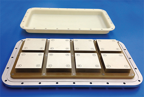
Composites and selective metallization allow higher levels of antenna integration. The aerospace industry, for example, is developing a highly modular approach to decentralized avionics known as the Mini-MRP, or Mini-Modular Rack Principle. One type of module is a wire access point for in-flight entertainment systems. A composite enclosure can not only include an embedded antenna, but connector shells, shielding and other features.
Selective metallization through conductive coatings offers a good way of creating circuit traces on composite parts that would more typically be etched using standard circuit board techniques. The conductivity of some coatings can approach the conductivity of bulk copper, adding minimal loss to the circuit while enabling more economical manufacturing. However, this selective metallization process particularly excels when applied to the manufacture of 3D circuit topologies. For example, it can make practical 3D RF couplers and direct-circuit connections to antennas.
Particularly in antenna assemblies for defense or aerospace applications, aluminum parts can account for a large portion of the total assembly weight. And the fabrication of aluminum parts entails significant machining time. Composite ground planes offer 30 to 40% weight savings over traditional aluminum parts. They are easy to manufacture and often cost much less than aluminum equivalents. Composite ground planes can be conductively coated if necessary to improve electromagnetic interference (EMI) shielding, grounding or protection from lightning strikes.
Similarly, traditional radome manufacturing historically involves tedious and slow hand layups of multiple material layers. The process becomes quite difficult for intricate radome shapes. Recent advances in long glass fiber and continuous glass fiber composites offer a means for eliminating the need for hand layups. Radomes can be thinner and lighter-weight when they are injection molded. The ability to mold strong, lightweight radomes represents a significant change in the economics of antenna design and fabrication. When necessary, 3D selective metallization can provide lightning diversion or frequency selectivity features to these radomes.
All in all, conductive coatings, injection-molded composites and selective metallization with conductive coatings combine to offer electrically and mechanically robust antennas and arrays in conformal, lightweight form factors. These advances in materials, processes and technology enable the size and weight reductions needed for next-generation antenna designs.
References
TE Connectivity
www.te.com