The classic wooden breadboard is obsolete, but its name continues to refer to a vital engineering tool that has changed to meet today’s component and design realities.
Breadboards have a special place and multiple meanings in the engineering lexicon. So, what is a breadboard? It can be a crude try-out version of a subcircuit to validate a concept or a fairly polished representation of the final system. It can be a test bed against which other parts of the system and software can be exercised or a test vehicle to understand better the attributes and characteristics of a component circuit functions.
The term breadboard is also often used in overlap with a related term, “prototype.” Although the terms are sometimes used interchangeably, they are somewhat different: a breadboard usually is a basic, often somewhat crude rendition of a desired circuit, while a true prototype is closer to the final design and may also deal with packaging, appearance, manufacturing issues (assembly and tolerance), and even qualification tests. As an obvious example, a breadboard may use an external power supply for convenience. At the same time, the prototype will usually incorporate the supply of the final product and its actual placement.
Given the relentless move to higher frequencies, it may seem that there is little room for basic breadboards and their rough layout since those frequencies are so sensitive to layout, parasitics, and other mysterious forces (even the ubiquitous FR-4 PC laminate is no longer adequate in many cases). But suppose you step back and look at what is in those designs. In that case, they usually also have a lot of lower-frequency analog and digital functions as well, with transducers for variables such as temperature, switch closures, pushbuttons, motors, and other tangible manifestations.
This article will look at the history of breadboards and some new implementations which are more suitable for the reality of many of today’s circuits and systems.
It really started with a breadboard
In the early days of electronics (in the early and mid-1920s), when self-powered crystal radios and even basic vacuum-tube radios were starting to reach individual experiments (they were not yet mass-market items), do-it-yourself (DIY) hobbyists and “makers” (that was before that word was in use as it is today) would build circuits on an actual breadboard, the wooden board used for cutting bread. They used tacks or nails as the connection points and wrapped the wires around them (perhaps a precursor of more-sophisticated wire-wrapping of the later 20th century), sometimes even soldering these connections (Figure 1).
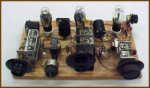
There was little need to worry about exposed wires with lethal voltages in those days (or you just had to be careful!), as most circuits used a 6- or 12-volt “A battery” for the tube filament and a series of batteries delivering around 50 volts for the tube’s plate – below or just bordering the level of danger. (Side note: that’s why we have no A or B batteries today, while we have AA, AAA, C, and D; the A and B designations were already in use.)
As experimental breadboarding became more popular, there was a need for a way to attach and remove wires easily, and push-down solderless clip-like connectors such as Fahnestock clips came into use (Figure 2). These were inexpensive, handy, easy to use, and – don’t be shocked – are still available, which is a testament to their utility.

The utility of these clips and similar arrangements came to a close with the introduction of solid-state devices. When discrete transistors and especially dual inline package (DIP) inserted circuits (ICs) arrived, the wood-based breadboard was no longer viable, but the word remained in standard use.
Part 2 will look at how breadboards transitioned for use with solid-state discrete devices and small-scale ICs.
EE World Related content
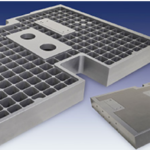
Mounting base kit simplifies electronic prototyping tasks
Understanding delay for I/O: Using Arduino functions vs. coding the MCU
Plug-And-Play Diagnostic Devices
Considerations in PCB layout guidelines
Getting started in electronics: core components
What is a Board Support Package?
A “canned” module/IC solution simplifies wireless implementation, but potential design-in issues remain
External references
Wikipedia, “Fahnestock clips”
Schmartboard Breadboard Systems
Phase Dock Inc., Universal WorkBench system