• Skip to primary navigation
  • Skip to main content
  • Skip to primary sidebar
  • Skip to footer

Analog IC Tips

Analog IC Design, Products, Tools Layout

  • Products
    • Amplifiers
    • Clocks & Timing
    • Data Converters
    • EMI/RFI
    • Interface & Isolation
    • MEMS & Sensors
  • Applications
    • Audio
    • Automotive/Transportation
    • Industrial
    • IoT
    • Medical
    • Telecommunications
    • Wireless
  • Learn
    • eBooks / Tech Tips
    • FAQs
    • EE Learning Center
    • EE Training Days
    • Tech Toolboxes
    • Webinars & Digital Events
  • Resources
    • Design Guide Library
    • Digital Issues
    • Engineering Diversity & Inclusion
    • LEAP Awards
    • Podcasts
    • White Papers
  • Video
    • EE Videos
    • Teardown Videos
  • EE Forums
    • EDABoard.com
    • Electro-Tech-Online.com
  • Engineering Training Days
  • Advertise
  • Subscribe

What is a cascode amplifier?

May 23, 2014 By Chris Francis 2 Comments

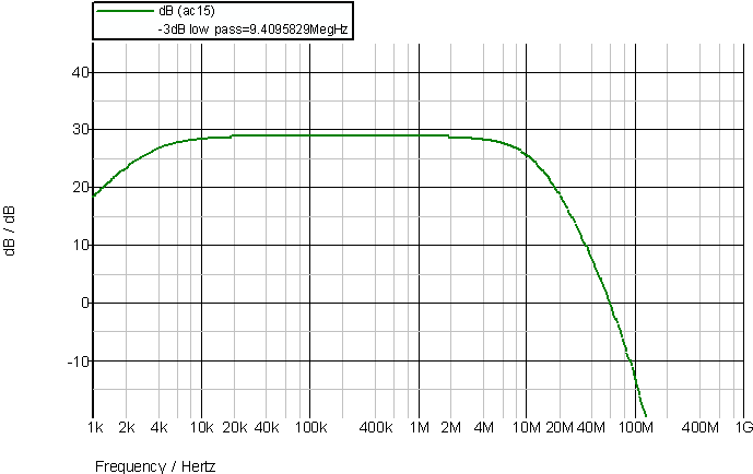
I am not sure how “fashionable” discrete transistor design is nowadays, but anyone using discrete transistors, bipolar or otherwise, for high speed designs other than for switching probably knows about cascode designs. The purpose of a cascode amplifier (not to be confused with cascade which is a chain of two or more amplifiers) is to isolate the Miller capacitance. Miller capacitance is the apparent multiplication of the base-collector or drain-source capacitance in an inverting amplifier. This can be simply explained due to the wider voltage swing of the collector (or drain). The effect of this voltage swing increases the apparent capacitance compared to visualizing the drain as being an AC ground. This can be illustrated in a simple example:


voltage swing


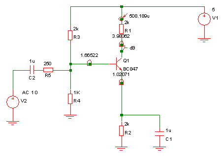
The performance of this circuit is shown below:

circuit performance


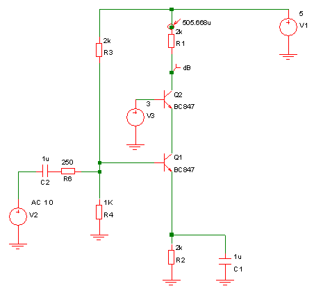
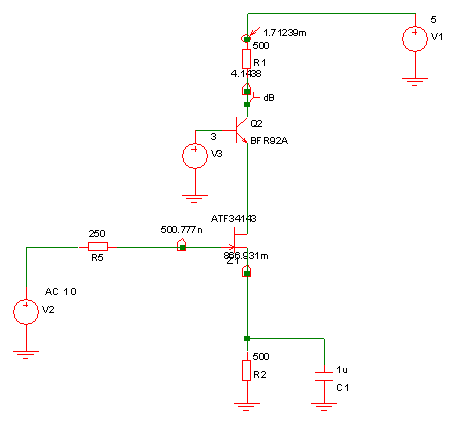
Adding a cascode while keeping the collector current the same:


cascode filter collector same

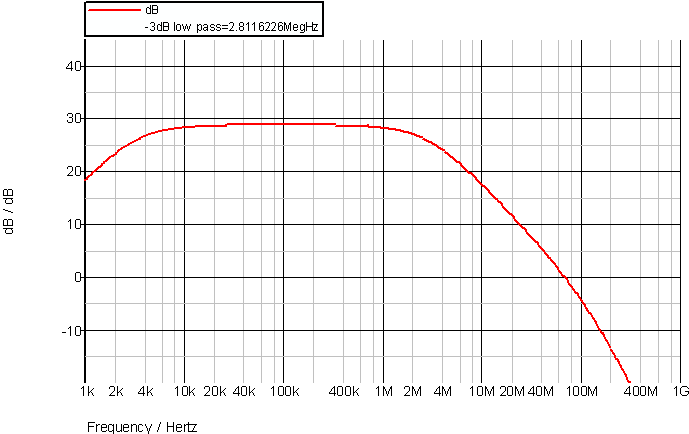
Gives the following results:


cascode results

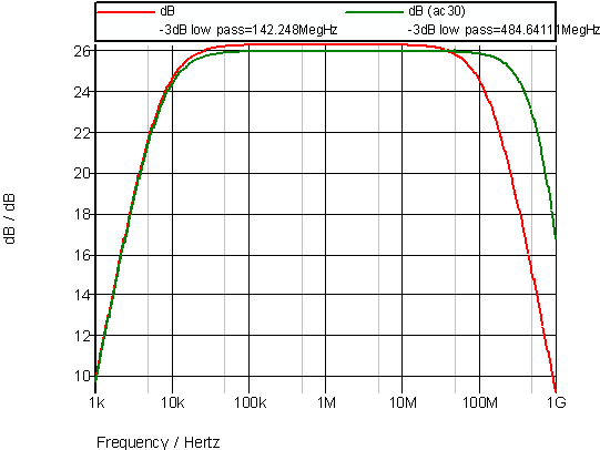
So, a more than three times improvement in 3dB bandwidth. The theoretical Miller effect would be to increase the base-collector capacitance by a factor of (1+ G) where -G is the gain of the stage. However, base-collector capacitance is not the only factor affecting the bandwidth so the bandwidth improvement is not the 28x you might hope for using that equation!

The improvement depends on the source impedance, load capacitance and gain as well as the characteristics of the device being used. The cascode transistor does not have to be the same part number as the amplifying transistor and in fact does not even have to be the same type. For example, you could use a bipolar cascode transistor with an HEMT (high electron mobility transistors) or GaAsFET:

GaAsFET


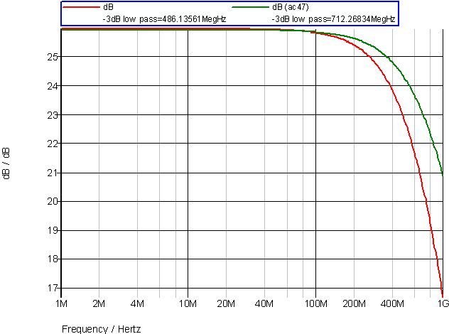
The improvement in bandwidth is shown below:

GaAsFET results


Not that these circuits are simply to illustrate the effect rather than being exact designs to follow. One important factor to keep in mind when adding a cascode transistor is that it takes some voltage headroom. You need to allow for this when deciding where to bias the base of the cascode transistor. Also, the base of the cascode needs to be held fairly solidly at a the chosen bias voltage. If you do not bias it with a low impedance and allow it to be dynamically moved around it will have undesirable effects.

The cascode amplifier can be viewed in different ways depending on your point of view. One way of looking at it is that the cascode transistor is simply that it passes the current through the emitter to its collector (less some base current) while preventing the emitter from moving, which is the important point. Another way of looking at the cascode is as a common base amplifier. A common base amplifier has a low input impedance which is the characteristic required to prevent the Miller effect on the common emitter gain stage – if the collector of the common emitter amplifier cannot move it cannot amplify the base-collector capacitance.

Depending on the characteristics of the individual devices it could be beneficial to use something other than a bipolar transistor for the cascode such as an HEMT. The graph below illustrates the improvement in bandwidth from using an HEMT for the cascode as well as the inverting amplifier transistor.

HEMT improvement

Filed Under: FAQ, Industry Experts, Interface & Isolation, Products Tagged With: basics, cascode design, FAQ

Reader Interactions

Comments

  1. Jerry Steele says

    July 18, 2014 at 6:06 pm

    There’s many reasons for cascoding, a common one is voltage ratings. I’m designing an audio amp right
    now using an Intersil (formerly RCA) transistor array at the front end (to get matched transistors) but it cannot
    handle the full 60 volt supply I’m using. So I cascode the collectors of the diff amp. Beauty is you can use crummy unmatched discretes with the voltage rating that you need.

    But then I’m one of the few nutcases left designing with discrete transistors anymore. I even combine NPN and PNP back to back for homemade SCR’s and DIACS (add a zener) just to save the lenghty drive to a parts store.

    Log in to Reply

Leave a Reply Cancel reply

You must be logged in to post a comment.

Primary Sidebar

Featured Contributions

Design a circuit for ultra-low power sensor applications

Active baluns bridge the microwave and digital worlds

Managing design complexity and global collaboration with IP-centric design

PCB design best practices for ECAD/MCAD collaboration

Open RAN networks pass the time

More Featured Contributions

EE TECH TOOLBOX

“ee
Tech Toolbox: Test & Measurement
We’ve gathered articles that include hands-on product tryouts and reviews. Indeed, every article in this issue uses an oscilloscope in one way or another so you might just call this “The Oscilloscope Tech Toolbox.”

EE LEARNING CENTER

EE Learning Center
“analog
EXPAND YOUR KNOWLEDGE AND STAY CONNECTED
Get the latest info on technologies, tools and strategies for EE professionals.

EE ENGINEERING TRAINING DAYS

engineering

RSS Current EDABoard.com discussions

  • Sedra smith example on low pass
  • Joint Webinar: AMD x iWave Global
  • Powering ADC using Buck Boost Converter
  • RF Transformer
  • PFC not in CCM

RSS Current Electro-Tech-Online.com Discussions

  • mechanism to shutdown feeding when sensor temperature rises
  • Want Thermal Camera with Fixed Thermal Span option
  • Bad design , bad maintenance or just how it was.
  • Looking for single photovoltaic cells for light gate
  • Sanity Check – Peltier "Cooler" for Heating and Cooling
“bills

Footer

Analog IC Tips

EE WORLD ONLINE NETWORK

  • 5G Technology World
  • EE World Online
  • Engineers Garage
  • Battery Power Tips
  • Connector Tips
  • EDA Board Forums
  • Electro Tech Online Forums
  • EV Engineering
  • Microcontroller Tips
  • Power Electronic Tips
  • Sensor Tips
  • Test and Measurement Tips

ANALOG IC TIPS

  • Subscribe to our newsletter
  • Advertise with us
  • Contact us
  • About us

Copyright © 2025 · WTWH Media LLC and its licensors. All rights reserved.
The material on this site may not be reproduced, distributed, transmitted, cached or otherwise used, except with the prior written permission of WTWH Media.

Privacy Policy