

Power ICs cover a variety of functions, from high voltage application-specific ICs (HV-ASICs) to power management ICs (PMICs). Each type of power IC has unique design challenges and needs specific design tools. This FAQ reviews some of the challenges related to HV-ASICs for applications like gate drivers for power semiconductor devices, pin drivers for automatic […]
FAQ
Design an analog front end for a pH probe
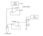
pH probes, with their bipolar voltage outputs and high output impedance, need signal conditioning through an analog front end to make them compatible with measurement circuits such as A/D converters. By Marian Hryntsiv, Renesas Electronics People who work in healthcare, food and beverage, water treatment, chemical processing, agriculture, and environmental monitoring rely on pH meters […]
What are the computational requirements of immersive audio?
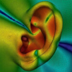
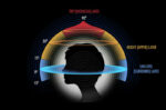
There are several ways to implement immersive audio, each with different computational and hardware needs. Calculation of the head-related transfer function (HRTF) is an important aspect of deploying immersive audio. This FAQ begins by detailing what an HRTF is, looks at an open-source program for calculating HRTF, and then considers how cameras and inertial measurement […]
What’s the difference between object- and channel-based audio?
Immersive audio uses various channel- and object-based techniques to deliver a high-quality listening experience. There are three general categories of spatial audio: channel-based audio (CBA), object-based audio (OBA), and scene-based audio (SBA) — that’s the next generation of OBA. CBA is the simplest form of spatial audio, but it’s not immersive. The basic form of […]
What codecs are there for immersive and 3D audio?
Immersive audio is a three-dimensional (3D) sound field created by combining lateral and overhead speakers. A variety of industry standard and custom codecs are available for implementing immersive audio. This FAQ reviews the operation of the MPEG-H Audio (universal immersive audio coding) codec and the still-under-development MPEG-I Immersive Audio (compressed representation for virtual and augmented […]
How does artificial intelligence relate to immersive audio?
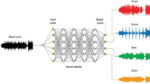
Tools like neural networks (NNs), machine learning (ML), and artificial intelligence (AI) are being applied to hard problems related to immersive audio. This FAQ will examine how NNs and ML are being used to up-mix audio tracks into their original constituent parts, how NNs are being used to produce personalized head-related transfer functions (HRTFs) and […]
What is immersive audio and how does it work?
Immersive audio extends conventional surround sound technology into the third dimension. It adds height and more to the audio experience. This FAQ presents some of the basic concepts of immersive audio, looks at how ambisonics relates to immersive audio, and closes by looking at a new recommended immersive audio system design practice. Immersive sound transforms […]
How many types of radar are there?

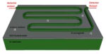
Radio detection and ranging (radar) uses reflected radio waves to detect and determine the distance, angle, and velocity of objects relative to the radar system. A basic radar system consists of a transmitter producing electromagnetic waves in the radio or microwave spectrum (these can be pulsed or continuous), a transmitting antenna, a receiving antenna (often […]
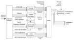
If you are working with sensors here are some tools to consider: Part 2
Sensor fusion is increasingly important across a range of applications including automotive, industrial, consumer, portable, medical systems and others. It can be challenging to sort out the design issues and identify the optimal solution. That’s where electronic design automation (EDA) tools are handy. The best choice of EDA tool or tools for a given project […]
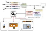
If you are working with sensors here are some tools to consider: Part 1
Sensor fusion is increasingly important across a range of applications including automotive, industrial, consumer, portable, medical systems, and others. It can be challenging to sort out the design issues and identify the optimal solution. That’s where electronic design automation (EDA) tools are handy. The best choice of EDA tool or tools for a given project […]