• Skip to primary navigation
  • Skip to main content
  • Skip to primary sidebar
  • Skip to footer

Analog IC Tips

Analog IC Design, Products, Tools Layout

  • Products
    • Amplifiers
    • Clocks & Timing
    • Data Converters
    • EMI/RFI
    • Interface & Isolation
    • MEMS & Sensors
  • Applications
    • Audio
    • Automotive/Transportation
    • Industrial
    • IoT
    • Medical
    • Telecommunications
    • Wireless
  • Learn
    • eBooks / Tech Tips
    • FAQs
    • EE Learning Center
    • EE Training Days
    • Tech Toolboxes
    • Webinars & Digital Events
  • Resources
    • Design Guide Library
    • Digital Issues
    • Engineering Diversity & Inclusion
    • LEAP Awards
    • Podcasts
    • White Papers
    • DesignFast
  • Video
    • EE Videos
    • Teardown Videos
  • EE Forums
    • EDABoard.com
    • Electro-Tech-Online.com
  • Engineering Training Days
  • Advertise
  • Subscribe

Choosing the right MEMS microphone interface for your project

April 3, 2019 By Aimee Kalnoskas

Micro-electro-mechanical systems (MEMS) microphones have been steadily increasing their market share, driven by the surge in popularity of voice-controlled electronics with applications like voice-enabled navigation devices and digital home assistants. But what are the different types of MEMS microphone electrical interfaces available and how do you apply them to your application?

A MEMS microphone with an analog output allows for an easy, uncomplicated interface with the host circuit. Driven by an internal amplifier, the microphone will already have reached a sufficient signal level with a relatively low output impedance. Common analog applications that benefit from this straightforward interface are simple loudspeakers or a radio communication system. In addition, this configuration is likely to exhibit lower power consumption than MEMS microphones with a digital output due to the absence of an analog-to-digital converter (ADC).

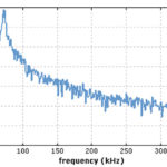
However, the addition of an ADC has its advantages, particularly when a digital output signal is delivered from a MEMS microphone and applied to digital circuitry, such as a microcontroller or digital signal processor. Output signals from MEMS microphones with a digital interface are also usually encoded with pulse density modulation (PDM) which is ideal where electrical noise immunity and bit error tolerance are concerned.

In this CUI Devices’ blog, CUI’s Principal Applications Engineer, Bruce Rose, compares the two most common MEMS microphone interfaces to help you select the one better suited for your design.

Read the full blog post here

You may also like:

  • MEMS and electret condenser
    A comparison of MEMS and electret condenser microphones
  • electrical noise
    Electrical noise, Part 1: Introductory concepts
  • active noise cancellation
    Active noise cancellation, Part 2: Implementation

  • Active noise cancellation, Part 1: Concept and principles

Filed Under: FAQ, Featured, MEMS & Sensors, Products Tagged With: cuidevices

Primary Sidebar

Featured Contributions

Design a circuit for ultra-low power sensor applications

Active baluns bridge the microwave and digital worlds

Managing design complexity and global collaboration with IP-centric design

PCB design best practices for ECAD/MCAD collaboration

Open RAN networks pass the time

More Featured Contributions

EE TECH TOOLBOX

“ee
Tech Toolbox: 5G Technology
This Tech Toolbox covers the basics of 5G technology plus a story about how engineers designed and built a prototype DSL router mostly from old cellphone parts. Download this first 5G/wired/wireless communications Tech Toolbox to learn more!

EE LEARNING CENTER

EE Learning Center
“analog
EXPAND YOUR KNOWLEDGE AND STAY CONNECTED
Get the latest info on technologies, tools and strategies for EE professionals.

EE ENGINEERING TRAINING DAYS

engineering

RSS Current EDABoard.com discussions

  • Diode recovery test Irrm timing.
  • How to make string LEDs?
  • The Analog Gods Hate Me
  • Battery Deep Discharge – IC Workarounds?
  • Safe Current and Power Density Limits in PCB Copper(in A/m² and W/m³) simulation

RSS Current Electro-Tech-Online.com Discussions

  • Raise your hand if your car had one of these:
  • Tektronix 2235 channel 1 trace unstable
  • How to make string LEDs?
  • Wideband matching an electrically short bowtie antenna; 50 ohm, 434 MHz
  • The Analog Gods Hate Me
“bills

Design Fast

Component Selection Made Simple.

Try it Today
design fast globle

Footer

Analog IC Tips

EE WORLD ONLINE NETWORK

  • 5G Technology World
  • EE World Online
  • Engineers Garage
  • Battery Power Tips
  • Connector Tips
  • DesignFast
  • EDA Board Forums
  • Electro Tech Online Forums
  • EV Engineering
  • Microcontroller Tips
  • Power Electronic Tips
  • Sensor Tips
  • Test and Measurement Tips

ANALOG IC TIPS

  • Subscribe to our newsletter
  • Advertise with us
  • Contact us
  • About us

Copyright © 2025 · WTWH Media LLC and its licensors. All rights reserved.
The material on this site may not be reproduced, distributed, transmitted, cached or otherwise used, except with the prior written permission of WTWH Media.

Privacy Policy