
Most electronics today have oscillators in them. Digital circuitry needs a clock. Radio frequency signals require an oscillator or clock. Some analog circuitry also needs a clock or oscillating signal source. If you are using a microcontroller then it might have a built-in clock, although it may not be accurate enough, depending on your application, so you may need to use an external crystal or clock module instead of being able to use the internal clock.
Digital oscillators
The circuitry of a digital oscillator is really an analog oscillator which clips, depending on how you look at it. Some oscillators actually produce a “clipped sine” output so it is difficult to decide which category to put them in – digital or analog. Digital oscillators can become more complicated than simply generating a single clock signal and may generate several signals with a defined phase shift or contain a frequency synthesizer to generate one or more alternative frequencies from a fixed frequency input clock. Look at some of the clock generator chips from IDT for example.
A common “digital” oscillator is the Pierce oscillator invented by George W. Pierce in 1923.
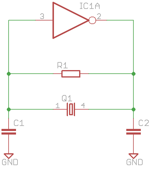
It has been used for a long time for microprocessor clock generation and when you have a microcontroller which requires a crystal and two external capacitors to generate its own clock, the chances are you are making a Pierce oscillator using the internal inverter and resistor (although you sometimes have to add the resistor yourself as well).
Choosing an oscillator module or clock generator means you need to understand the choices available and you need to specify your requirements.
Output definition
The output may be square or a clipped sine wave (rarely a true sine for a digital system). You need to know what voltage levels you require e.g. 5V TTL or CMOS levels, 3.3V or lower CMOS levels. Some oscillators have low voltage differential signaling outputs (LVDS). Symmetry is often important so the high an low phases are equal (say 45%:55% worst case.
Accuracy and stability
You need to know what accuracy and stability you require. With a ceramic resonator you can get an initial tolerance of around 0.2% although often worse than that. While 0.2% doesn’t sound too bad, it is 2000ppm (parts per million). Quartz crystal based oscillators will be 10 times better than that, usually more. Similarly a quartz based oscillator will have better stability than a ceramic resonator based one. Stability can be defined as temperature, load or supply stability – all of which can affect the frequency.
A TCXO is a Temperature Compensated Crystal Oscillator or Temperature Controlled Crystal Oscillator (the word crystal is often abbreviated to Xtal so X is used as an abbreviation of “crystal”). These can have tolerance and stability considerably better than 1ppm. Such accuracies are important for RF (radio frequency) systems where frequencies are required to be very precise.
A VCXO is a voltage controlled crystal oscillator and usually allows the frequency to be “pulled” by a small amount while still having high stability. Frequency adjustment range is usually limited to maybe 200ppm.
An OCXO is “oven controlled”. These have the oscillator in an oven or a double oven where the circuitry and crystal are heated to a constant temperature. Once warmed up they are very precise and stable. They do take a fair amount of power though due to the heater required.
Analog oscillators
For an analog oscillator you are more likely to be looking for a sine wave. There are various “standard” analog oscillator designs which have been around since before transistors existed. Hartley, Colpitts and Clapp for example. These have been used as sine wave oscillators using inductors and capacitors as the frequency determining component and also with quartz crystals. They can also be used as variable frequency oscillators when used with inductors/capacitors. Other oscillators such as the Wien bridge use resistors and capacitors to determine the frequency but are generally limited to lower frequencies than inductor/capacitor or crystal oscillators.
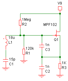
As an example, this is a 10MHz Clapp oscillator with the output being taken from the source of the transistor Q1.
One thing to bear in mind with all oscillators is that they take time to start. With high Q oscillators such as crystal oscillators this can be quite significant as the startup time (measured in number of clock cycles) is proportional to the Q of the circuit. This can result in a significant delay before anything seems to happen and can also result in the frequency being incorrect initially. For example, this is the startup of a 50MHz LC oscillator which takes around 800 clock cycles to start:
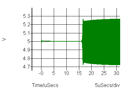
While it looks like nothing is happening to begin with, if you zoom in on the initial section you will see that something is actually happening. It takes a lot of cycles for the phase to adjust for the oscillation conditions to be met, depending on the Q of the resonant circuit. Then they can seem to burst in to life.