Sound is an analog or linear phenomenon. Traditional audio amplifiers such as Class A and Class AB operate the amplifying transistors in the linear mode. Class A and AB amplifiers can provide clean sound, but are inefficient, like linear power supplies. Class D amplifiers are similar to switched-mode power supplies and use various pulse modulation techniques to deliver clean amplified sound with higher efficiencies compared with their linear Class A and AB counterparts.
Like switch-mode power supplies, Class D amplifiers require a different type of power transistor, one optimized for fast and efficient switching. Class D amplifiers also have more complex control schemes compared with relatively simple Class A or AB amplifiers. The return on the investment in faster switches and more complex control is amplifiers that are smaller, cooler and can extend battery life in portable systems.
While they offer superior operating characteristics in several regards, Class D amplifiers can still suffer from limitations and tradeoffs:
- Need for an LC filter increases size, this can be particularly troublesome in space-constrained devices
- Need for an LC filter adds to cost
- Relative inefficiency at typical listening levels
- Thermal management issues can arise due to inefficiencies at typical power levels
More efficient, but not perfect
Class D amplifiers can reach peak efficiencies of 90% or greater. That compares with peak efficiencies of about 30% for Class A amplifiers and about 60% for Class AB amplifiers. And Class D amplifiers are more efficient than A or AB over the entire output power range. But, like all amplifiers, Class D amplifiers are significantly less efficient when operated below the peak rated power.
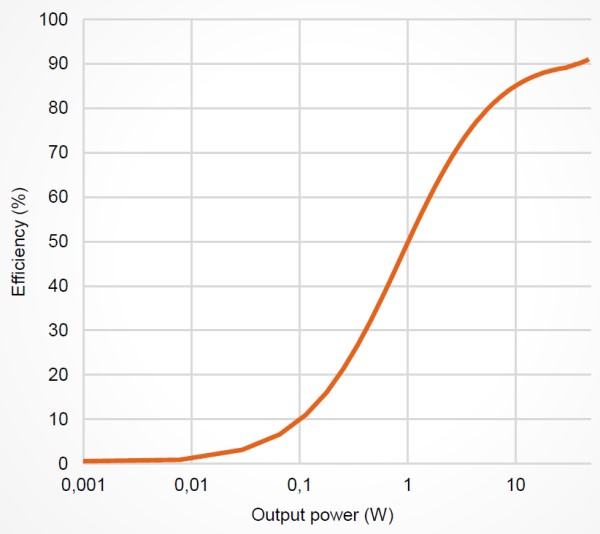
The figure below graphs the efficiency of a traditional class D amplifier. The horizontal axis is plotted on a logarithmic scale to emphasize the lower end of the output power scale. For typical listening levels of 0.1 to 1 Watt of output power per channel, efficiency barely reaches 50 percent (Class A and AB amplifiers are much less efficient in this region). The headroom above 1 Watt is typically used to deliver the peak power, which is required now and then to reproduce the music accurately. The figure shows that a traditional class D amplifier can reach 90 percent efficiency, but only for levels above 10 W (in this case, up to 40 W) — levels that are rarely reached by real-life audio signals for extended time-intervals.
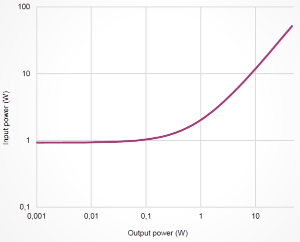
At the lower end of the power output scale, the overall efficiency is dominated by the power consumption (input power) of the amplifier in the idle condition— i.e., the power consumption of the amplifier when it is not producing any output.
The figure below shows idle power consumption at close to 1 W for a conventional class D amplifier, which is running on an 18V power rail. Due to the less than ideal curve shape, the audio amplifier easily dominates power consumption of the complete audio system – not just at high output volumes but even between idle and medium output volumes.
So, while Class D amplifiers are more efficient compared with Classes A and AB, there is still room for improvement, especially at lower output power levels. Several techniques have been developed to improve the efficiency of Class D amplifiers at lower output powers. Multi-level output topologies and so-called Class D boosted designs that incorporate Class H amplifier (envelope tracking) techniques can improve the low-power efficiency of Class D amplifiers. But those increases in efficiency can come with increased complexity and more cost.
Single-ended or differential topology?
Like conventional switch-mode power supplies, traditional Class D amplifiers can be half-bridge (single-ended) or full-bridge (differential) topologies. The half-bridge Class D amplifier illustrated below consists of a pulse-width modulator, two output MOSFETs, and an external lowpass filter (LF and CF) to recover the amplified audio signal. As shown in the figure, the p-channel and n-channel MOSFETs operate as current-steering switches by alternately connecting the output node to VDD and ground. Because the output transistors switch the output to either VDD or ground, the resulting output of a Class D amplifier is a high-frequency square wave.

A full-bridge uses two half-bridge stages to drive the load differentially. This type of load connection is often referred to as a bridge-tied load (BTL). As shown below, the full-bridge configuration operates by alternating the conduction path through the load. This allows bidirectional current to flow through the load without the need of a negative supply or a DC-blocking capacitor. As with the half-bridge topology, an external LC filter is needed at the output to extract the low-frequency audio signals and prevent high-frequency energy from being dissipated in the load.
Regardless of the topology, there are two primary modulation techniques used in Class D amplifiers; pulse width modulation (PWM) and pulse density modulation (PDM). Each of these modulation techniques involves tradeoffs. PWM running on a fixed frequency is digital implementation friendly, makes it easier to handle errors from finite switching times, and offers better EMI emission characteristics. PDM is great for having higher loop gain and achieving better audio performance. PDM also has the advantage of reduced switching loss and a better voltage utilization ratio.
References
ASX Series Class D amplifiers, ICEpower
Class D Audio Amplifiers, Efficient Power Conversion
MERUS™ multilevel class D audio amplifier supports ultra-compact and low-power applications, Infineon
Fundamentals of Class D Amplifiers, Maxim Integrated Products
Class-D amplifier, Wikipedia