The performance of a clock function, which includes the crystal and associated circuitry, is defined by parameters which are measured over both the short term and long term. It is also characterized by change in specifications due to temperature variations, aging, and mechanical considerations such as vibration and shock.
How is clock performance defined?
Both time domain and frequency domain numbers are used. Neither is “more correct”, as they are really two equally legitimate perspectives of the same phenomena, but it is a matter of context and ease of associating the parameter value with the observation and its consequences. Also, the numbers are often specified with peak, average, or rms qualifiers, as different applications have different concerns.
What is the first parameter of interest?
For most clock applications, the first number is frequency, of course. Closely aligned with this is the accuracy of that initial frequency value, given as a percent (such ±0.1%), parts per million (ppm), or an absolute number (5 MHz ± 10 kHz).
What are other key clock parameters?
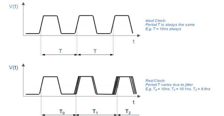
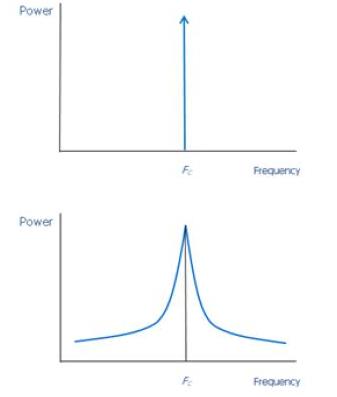
Jitter and phase noise are two of the top-tier parameters. Jitter can be observed and defined in both the time domain (Figure 1) and the frequency domain (Figure 2), where it is seen as phase noise. Again, time and frequency domains are equally valid ways of looking at the same phenomena, and depending on the application and analysis, one perspective may be more revealing than the other.
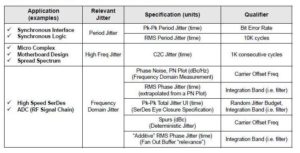
What are the sources of jitter?
Jitter is a complicated topic, having many sources and system implications. It can be due to imperfections in the clock source (usually a crystal, but can be a master clock); any associated oscillator, internal noise, external noise, circuit-board crosstalk and EMI; and other factors. There are many types of jitter and units for measuring it, such as time or unit intervals, Table. In today’s high-speed and wideband systems, jitter is usually in the range of picoseconds or less, or in thousandths of a unit interval (UI), where a UI is a single clock cycle.
Where is short-term jitter a critical factor?
It jitter was just minute variations in the rate at which a processor or FPGFA is being clocked, it would not be a major concern. But is it a major issue when the clock is timing data pulses on a wired or wireless link, since these bits must be precise and timed with great stability for both system-wide and receiver performance.
Clock jitter is also a major concern for sampled-data systems, where a communications channel digitizes the signal at rates into the hundreds of MHz and above, or where the clock is used to establish a carrier frequency. In these cases, jitter shows up as distortion on the signal, artifacts on the carrier, and spurious frequencies (spurs) on either side of the nominal carrier of sampled data. The result is data errors and even interference with other channels.
What other factors may be critical?
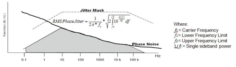
The shape of the clock is also critical when used to drive processors and FPGAs, with vendor-specified requirements on rise time (defined as 20% to 80% transition), fall time (80% to 20%), and duty cycle (which is usually between 40% and 60%). To assess this jitter, phase-noise masks are used to define the boundaries of acceptable jitter performance, Figure 3.
What about stability, and long-term and drift factors?
All clocks – the combination of the crystal and associated oscillator circuit – undergo changes in the accuracy and stability of their frequency and other parameters due to changes in temperature, aging of the crystal, shock and vibration, and mechanical stresses. Whether these will be a concern depends on the application.
For a low-end application such as a personal timepiece (watch), a drift of several seconds per month is acceptable. With higher-speed data links, however, even minuscule changes over time have serious negative implications. These instabilities of longer-term fluctuations and drifts are specified per hour, day, week, and even year, depending on the target application.
What can be done to maximize precision, minimize clock drift, and enhance stability? There are many tactics used:
- The clock components, especially re crystal, can have their aging accelerated by operating at higher temperature before use; this is called “bake in”;
- Special components with low temperature coefficients can be used, while the physical cut of the quartz crystal itself is a major factor here;
- The crystal and circuit can be placed in a small oven in operation, which maintains a fixed temperature in what is called an OXCO (oven controlled crystal oscillator), but this obviously requires additional power and increases dissipated heat, which is a drawback;
- The entire design be done as a temperature-compensated crystal oscillator (TXCO) , where the operating temperature is measured and then operating points are shifted accordingly via a VCO (voltage controlled oscillator);
- Digital correction is an advanced option, where calibration and drift-compensation factors are measured in advance, and then programmed into a table which is used to correct imperfections via a closed-loop circuit;
- To minimize changes due to shock and vibration, crystals are available with special mountings and housings designed to absorb these mechanical effects;
- To minimize the effects of moisture, the entire assembly can be packaged in a hermetically sealed housing that is filled with dry air or inert gas.
Although apparently a simple manifestation of the piezoelectric principle, the clock is a critical element defining a system’s ultimate performance. It has many subtle aspects and complexities in practice, with different dimensions, perspectives, figures of merit, imperfections, and areas of concern, all related to the target application.
References
- AN-815, “Understanding Jitter Units,” http://www.idt.com/document/apn/815-understanding-jitter-units, (IDT)
- AN-827, “Application Relevance of Clock Jitter,” http://www.idt.com/document/apn/827-application-relevance-clock-jitter, (IDT)
- AN-839, “RMS Phase Jitter,” http://www.idt.com/document/apn/839-rms-phase-jitter
- AN-840, “Jitter Specifications for Timing Signals,” http://www.idt.com/document/apn/840-jitter-specifications-timing-signals , (IDT)
- AN-827, “Application Relevance of Clock Jitter,” https://www.idt.com/document/apn/827-application-relevance-clock-jitter , (IDT)