• Skip to primary navigation
  • Skip to main content
  • Skip to primary sidebar
  • Skip to footer

Analog IC Tips

Analog IC Design, Products, Tools Layout

  • Products
    • Amplifiers
    • Clocks & Timing
    • Data Converters
    • EMI/RFI
    • Interface & Isolation
    • MEMS & Sensors
  • Applications
    • Audio
    • Automotive/Transportation
    • Industrial
    • IoT
    • Medical
    • Telecommunications
    • Wireless
  • Learn
    • eBooks / Tech Tips
    • FAQs
    • EE Learning Center
    • EE Training Days
    • Tech Toolboxes
    • Webinars & Digital Events
  • Resources
    • Design Guide Library
    • Digital Issues
    • Engineering Diversity & Inclusion
    • LEAP Awards
    • Podcasts
    • White Papers
  • Video
    • EE Videos
    • Teardown Videos
  • EE Forums
    • EDABoard.com
    • Electro-Tech-Online.com
  • Engineering Training Days
  • Advertise
  • Subscribe

Clock Tree 101

July 18, 2016 By Aimee Kalnoskas Leave a Comment

By Linda Lua, Silicon Labs

What is a clock tree?
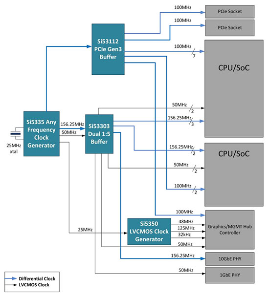
A clock tree is a clock distribution network within a system or hardware design. It includes the clocking circuitry and devices from clock source to destination.

The complexity of the clock tree and the number of clocking components used depends on the hardware design. Since systems can have several ICs with different clock performance requirements and frequencies, a “clock tree” refers to the various clocks feeding those ICs.

It’s often the case that a single reference clock will be cascaded and synthesized into many different output clocks, resulting in a diagram that looks a bit like a sideways tree trunk. The “trunk” is the reference clock and the “branches” are the various output clocks.

timer-clock-tree-101-fig1
Fig.1 – Example “Clock Tree”

Clock trees can be both very complex with many timing components or very simple with a single reference and a few copies. Of course, their complexity depends on the system they support. While there are many timing component types for many different types of applications, the most common timing components are:

– Crystals – a piece of quartz or other material that resonates in a predictable pattern at a given frequency when used in conjunction with an on-chip voltage oscillator circuit;

– Crystal Oscillators (XOs) – a self-contained resonator and oscillator that outputs a given frequency and format;

– Voltage controlled oscillators (VCXOs) – a self-contained oscillator that varies its output frequency in concert with differing voltages from a voltage reference;

– Clock Generators – an integrated circuit that uses a reference clock or crystal to generate multiple output clocks at one or multiple frequencies;

– Clock Buffers – an integrated circuit that creates copies or derivatives of a reference clock; – Jitter Attenuators or Jitter Cleaners – an integrated circuit that removes jitter (noise) from a reference clock.

Read Full Article

Filed Under: Clocks & Timing, Industry Experts, Products Tagged With: mouser, siliconlabs

Reader Interactions

Leave a Reply Cancel reply

You must be logged in to post a comment.

Primary Sidebar

Featured Contributions

Design a circuit for ultra-low power sensor applications

Active baluns bridge the microwave and digital worlds

Managing design complexity and global collaboration with IP-centric design

PCB design best practices for ECAD/MCAD collaboration

Open RAN networks pass the time

More Featured Contributions

EE TECH TOOLBOX

“ee
Tech Toolbox: Connectivity
AI and high-performance computing demand interconnects that can handle massive data throughput without bottlenecks. This Tech Toolbox explores the connector technologies enabling ML systems, from high-speed board-to-board and PCIe interfaces to in-package optical interconnects and twin-axial assemblies.

EE LEARNING CENTER

EE Learning Center
“analog
EXPAND YOUR KNOWLEDGE AND STAY CONNECTED
Get the latest info on technologies, tools and strategies for EE professionals.

EE ENGINEERING TRAINING DAYS

engineering

RSS Current EDABoard.com discussions

  • Charge Pump Design for a 'DC' type Output
  • problem with Stb simulation for an integrator
  • Why spread inductor turns across the bobbin?
  • tv crt glass
  • 9V~36V 200W output isolated DCDC converter from PFC 400V, which topology will you choose?

RSS Current Electro-Tech-Online.com Discussions

  • Steering angle sensor question
  • Sine wave distortion
  • Variable audio oscillator
  • potenciometer attachment / screwdriver
  • flexible copper cable
“bills

Footer

Analog IC Tips

EE WORLD ONLINE NETWORK

  • 5G Technology World
  • EE World Online
  • Engineers Garage
  • Battery Power Tips
  • Connector Tips
  • EDA Board Forums
  • Electro Tech Online Forums
  • EV Engineering
  • Microcontroller Tips
  • Power Electronic Tips
  • Sensor Tips
  • Test and Measurement Tips

ANALOG IC TIPS

  • Subscribe to our newsletter
  • Advertise with us
  • Contact us
  • About us

Copyright © 2026 · WTWH Media LLC and its licensors. All rights reserved.
The material on this site may not be reproduced, distributed, transmitted, cached or otherwise used, except with the prior written permission of WTWH Media.

Privacy Policy