Almost every engineer who has to deal with real-world signals, analog sensors, front-end circuitry, filtering, line drivers/receivers, or general amplification is familiar with the basic operational amplifier (op amp) which is the building block of most analog circuity. These op amps generally use voltage feedback (VFB), and have been studied and used extensively.
However, there is analogous class of op amps called current feedback (CFB) amplifiers which share some VFB characteristics but also differ in other key ones. This FAQ will look at the principle of CFB amplifiers and key attributes, as well as similarities and differences compared to VFB units. It will also look at how applications leverage the characteristics of CFB topology.
Q: What is a current feedback amplifier and what is its “black box” input/output relationship?
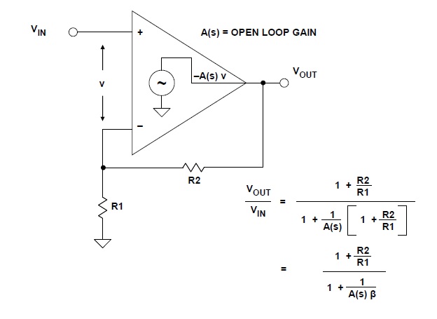
A: Before answering that question, let’s review the better-known VFB amplifier. The simplified model of the widely used VFB op amp, Figure 1, leads to standard gain equations. As a result of the applied negative feedback, the op amp’s “action” is to drive the error voltage to zero, thus the designation “voltage feedback.”
Q: So what happens in a CFB design?
A: In a CFB op amp, as modeled in Figure 2, the negative feedback causes the op amp to drive the error current to zero; so it is termed “current feedback.” The well-known gain relationships remain unchanged: the inverting gain is still –Rf/Rin, and the noninverting gain is still 1+Rf/Rin.

Q: What is the internal operation of the CFB design?
While you generally do not need to deal with internal details, it may be helpful to better understand them if design issues arise. In the basic topology of the figure, a unity-gain buffer connects the non-inverting input to the inverting input. The output impedance of this buffer (ideally) is zero (RO = 0), and the error signal is a small current, i, which flows into the inverting input.
The error current is mirrored into a high impedance, T(s) (generally referred to as the open-loop transimpedance gain), and the voltage developed across T(s) is to T(s) × i. If RO is assumed to be zero, the closed-loop gain equation VOUT/VIN is expressed in terms of the R1-R2 feedback network and the open-loop transimpedance gain, T(s).
Q: Are there any terminology issues of which to be aware?
A: Current-feedback op amps are often called “transimpedance” op amps, because the open-loop transfer function is an impedance. However, the transimpedance amplifier designation is better applied to more general circuits such as current-to-voltage (I/V) converters, where either CFB or VFB op amps can be used. Therefore, it’s a good idea to be careful when the term transimpedance is used in an application. In contrast, the term “current feedback op amp” is rarely confused and is the preferred terminology when referring to op-amp topology.
Q: Why even consider a CFB amplifier?
A: The CFB topology is primarily used where the most in high speed and low distortion is required. The reason is that currents in bipolar transistor circuits can be switched faster than voltages, all other things being equal. The current-feedback architecture has very high slew rate and the small-signal bandwidth is fairly constant for all gains. Current feedback amplifiers are used in broadcast video systems, radar systems, IF and RF stages, RGB distribution systems, and many other high-speed circuits.
Q: What are some other important CFB attributes?
A: In VFB op amp circuits, the gain-bandwidth product is constant over the specified operating- frequency range. In contrast, in CFB op amp circuits the gain and bandwidth can be independently set.
The CFB model also points to some other characteristics:
- Unlike VFB op amps, CFB op amps do not have balanced inputs. Instead, the non-inverting input is high impedance, and the inverting input is low impedance.
- The open-loop gain of CFB op amps is measured in ohms (transimpedance gain) rather than V/V as it is for VFB op amps.
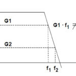
- With feedback resistor R2 at a fixed value, the closed-loop gain of a CFB can be adjusted by changing R1 without significantly affecting the closed-loop bandwidth (demonstrated by the equation of Figure 3). The denominator determines the overall frequency response; if R2 is constant, then R1 of the numerator can be changed (thereby changing the gain) without affecting the denominator. As a result, the bandwidth remains relatively constant.
Q: Should I “fear” the CFB op amp?
A: No! The term “current feedback” refers to the internal operation of the op amp, not some new or exotic way of connecting the output back to the input. The standard gain arrangements are unchanged. Again, the inverting gain is remains –Rf/Rin, and the noninverting gain is remains 1+Rf/Rin.
Part 2 of this FAQ will look in more detail at using VFB versus CFB op amps and some of the tradeoffs between them. The References explore the use and design-in issues of CFB op amps, in addition to providing more details on their transfer function, models and principles.
References
- Analog Devices, MT-034 Tutorial, “Current Feedback (CFB) Op Amps”
- Texas Instruments, Application Report SLOA066, “Current Feedback Op-Amp Circuit Collection”
- Texas Instruments, Application Report SLVA051, “Voltage Feedback Vs Current Feedback Op Amps Application Report”
- Linear Technology Corp., Design Note 46, “Current Feedback Amplifier ‘Do’s and Don’ts’”