I thought I would share some of the crimes against filters that I have seen people commit over the years.
2+2=4?
So, you have designed a 2 pole Butterworth filter for example and want a 4 pole one so you put two of them together. You have a four pole filter? Yes, but not a Butterworth filter! The schematics of a 4 pole filter and a cascade of two 2 pole filters might look identical but the component values will be different. This can be illustrated below
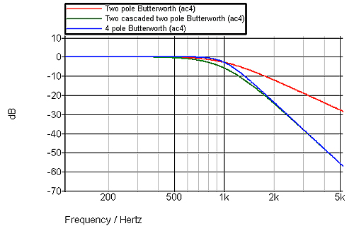
The design of the various filter types such as Butterworth, Chebyshev, Bessel etc creates a certain characteristic which is not based on simply repeating identical stages but selecting the Q of stages to give the desired cut-off characteristic. While the basic filter types will have 20dB/decade per pole it is the way that they get there that is important, as well as the corresponding transient response and/or group delay and phase response.
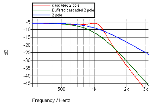
The situation is worse with a passive filter if you don’t remember the fact that a simple 2 pole LC needs a source and load impedance. If you cascade two passive LC filters, not only will you not get the desired response due to the fact that a 4 pole filter isn’t a simple cascade of two identical 4 pole designs, you will also see the effects of the interaction of the two stages.
Below is shown the effect of cascading two identical LC 2 pole filters and also showing the effect of a buffer with a gain of 2 (with source/load resistors) between the two stages. Even that is not a good filter design but avoids the peaking caused by mismatching the source and loads of the two stages.
Variable Gain
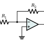
The commonly used Sallen & Key filter is a unity gain version of the “single amplifier biquad” (SAB). With a SAB filter you can have some gain. However, once you have designed the filter and chosen the component values you cannot use it as a variable gain stage. At best it will be the wrong response, at worst it will be an oscillator. While it may seem obvious, I have seen people make this mistake on more than one occasion.
Don’t forget about opamp bandwidth
While the Sallen & Key and SAB filters are commonly used, you must remember that the bandwidth requirement of the opamps can get very high as the number of poles increases. The free software from Texas Instruments – FilterPro – shows this bandwidth requirement and it shouldn’t be ignored otherwise you will not get the filter response you want, nor will you get the cut-off frequency you want. As an example, a 6 pole Chebyshev 1dB ripple filter with 1kHz cut-off needs a 51MHz opamp bandwidth if you use a Sallen & Key filter. By contrast, the “Multiple Feedback” design needs 800kHz. That is one of the reasons that the Sallen & Key filter, while popular, is not always the best choice for higher numbers of poles.
Remember Component Tolerances
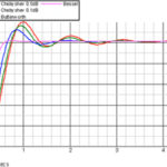
The first problem after designing a filter is finding the nearest component value to the one you need and making sure that it doesn’t affect the filter design significantly. If you have some cost constraints then you will be avoiding very expensive capacitors and probably avoiding E192 0.1% resistors. Some filter topologies are more sensitive to component tolerances than others. Whichever topology you use, you must remember to check the effect of component tolerances. Below is a 4 pole 0.5dB Chebyshev with a nominal cut-off of 11kHz (green trace) and the results of 100 Monte Carlo runs to look at the likely effect of component tolerances.
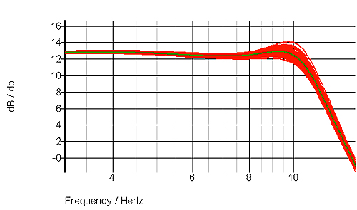
As you can see, it is not a 0.5dB ripple Chebyshev any more. The real situation could be worse because a Monte Carlo analysis is not a “worst case”. The filter design software from Nuhertz will give a sensitivity analysis for each component so you can see the effect on gain, phase and group delay. There is a free version of the Nuhertz software but it is limited and doesn’t have the sensitivity analysis.
Source/Load Impedances
Depending on the filter design you may not have a problem with source/load impedances but most filters don’t have an infinite input impedance so if your signal source hasn’t a very low impedance relative to the filter impedance it will need buffering first. If you are designing a passive LC filter, don’t forget to check the effect of the series resistance of the inductors.