Digital potentiometers – digipots – are widely used, versatile, flexible, and feature-laden alternatives to classic mechanical potentiometers.
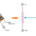
In a traditional potentiometer, a person’s hand (or perhaps even a small motor) sets the wiper position and thus the voltage-division ratio. In a digipot, instead, a computer and digital interface connect to the digipot IC and establish an equivalent to the wiper position (Figure 1).
The digipot uses standard CMOS IC technology and does not require special fabrication or handling. A digipot can be packaged as a surface-mount IC as small as 3 × 3 mm or even less and so is far smaller than a knob-adjusted potentiometer or even a small screwdriver-adjusted “trimpot”, (a miniaturized potentiometer used for one-time calibration). It is handled just like any other SMT IC with respect to PC-board production.
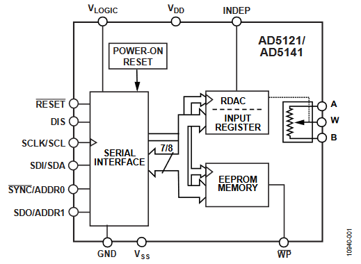
Conceptually, the internal topology of the digipot consists of a serial string of resistors with digitally addressable electronic switches between the wiper and these resistors. Via digital command, the appropriate switch is turned on while others are turned off, thus establishing the desired wiper position. In practice, this topology has some drawbacks, including a large number of resistors and switches needed and a larger die size. Vendors have devised clever alternative resistor and switch arrangements which reduce the number of resistors needed while still yielding the same effect.
Digipots offered range of specifications, features
As with any component, there are top-tier parameters and secondary ones to consider when selecting a digipot. The first-rank issues are nominal resistance value, resolution, and type of digital interface, while considerations include tolerance and error sources, voltage range, bandwidth, and distortion.
- The required resistance value, often called end-to-end resistance, is determined by the design considerations of the circuit. Vendors offer resistances between 5 kΩ and 100 kΩ in a 1/2/5 sequence with some other intermediate values, and there are extended-range units that go as low as 1 kΩ and as high as 1 MΩ.
- Resolution defines how any discrete step or tap settings the digipot offers and can range from 32 to 1024 steps to allow the designer to match the application’s needs. Keep in mind that even a mid-range 256-step (8-bit) digipot has a higher resolution than a potentiometer.
- The digital interface between the microcontroller and the digipot is available in standard serial SPI and I2C formats and address pins to connect multiple devices via a single bus. The microcontroller uses a simple data-encoding scheme to indicate the desired resistance setting.
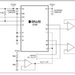
There are digipots interface variations simplify their use in applications such as user-operated volume controls via options such as the pushbutton and the up/down (U/D) interface. With the pushbutton interface, the user pushes one of two available buttons to increment the resistance count and the other to decrement it; note that there is no processor involved in this action (Figure 2).
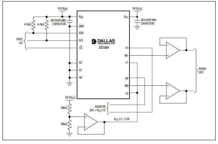
The up/down interface can be implemented with minimal software overhead and is triggered via a simple rotary encoder or pushbutton connected to a processor action (Figure 3).

- Tolerance for digipots may be an issue as it is typically between ±10 and ±20% of nominal value, which is acceptable in many ratiometric or closed-loop cases. However, it can be a critical parameter if the digipot is matched to an external discrete resistor or a sensor in an open-loop application. For this reason, there are standard digipots with much-tighter tolerance as low as ±1%.
Of course, as with all ICs, the temperature coefficient of resistance and resultant drift can also be a factor. Vendors specify this number in their datasheet so designers can assess its impact via circuit models such as Spice. (Other tight-tolerance options are available and are discussed below.)
- Although not a concern in static applications such as calibration or bias-point setting, available bandwidth and distortion issues in audio and related applications. The resistance path of a particular code, combined with the switch parasitics as well as the pin and board capacitances, creates an RC low-pass filter that determines the 3-dB bandwidth frequency. Lower end-to-end resistor values yield a higher bandwidth, with bandwidths up to about 5 MHz for a 1-kΩ digipot to 5 kHz for a 1-MΩ unit.
In contrast, total harmonic distortion (THD) is mainly due to resistance nonlinearities at different applied signal levels. Digipots with higher end-to-end resistance reduces the contribution of the internal switch resistance versus the total resistance, resulting in lower THD. Thus, bandwidth versus THD is a tradeoff that the design engineers must prioritize and weigh when choosing the nominal digipot value. Typical values range from -93 dB for a 20-kΩ digipot down to -105 dB for a 100-kΩ unit.
Thus far, we have looked only at basic digipots and their attributes. The next section looks at some additional features these devices offer.
Conclusion
The digipot is a digitally set IC that replaces the classic rotary-knob electromechanical potentiometer in many system architectures and circuit designs. It reduces product size, but it also adds compatibility with processors and thus software while offering greater accuracy and higher resolution (if needed) and other useful features. Digipots are available in a wide range of nominal resistance values, step sizes, and accuracies. At the same time, the addition of nonvolatile memory extends their capability and overcomes an important barrier to their use in many products.
Related EE World Content
What is a digital potentiometer?
What’s a logarithmic resistor ladder good for?
Advanced IC integrates instrumentation amp, auto-trimming, digital pots, analog switches
Single-turn potentiometers, encoders excel at rugged industrial apps
Micro-sized slide potentiometers for consumer, audio, medical, or industrial applications
References
VivaDifferences.com, “10 Differences Between Potentiometer And Rheostat (With Comparison Chart)”
Maxim Integrated Products, “Digipot Application Ideas”
Maxim Integrated Products, Application Note 1956, “Tips to Remember When Designing with Digital Potentiometers”
Maxim Integrated Products, Tutorial 1828, “Audio Gain Control Using Digital Potentiometers”
Maxim Integrated Products, Application Note 4051,” Using an Analog Voltage to Control a Digital Potentiometer”
Components101, “How does Digital Potentiometers work, why and where should you use them?”
Analog Devices, “Choosing the Correct digiPOT for Your Application”
Microchip Technology, AN691, “Optimizing Digital Potentiometer Circuits to Reduce Absolute and Temperature Variations”
Microchip Technology, AN1316, “Using Digital Potentiometers for Programmable Amplifier Gain”
Microchip Technology, AN1080, “Understanding Digital Potentiometers Resistor Variations”
Microchip Technology, “Digital Potentiometers Design Guide”