Op Amps or operational amplifiers, are fundamental building blocks in electronic design, mainly because these analog integrated circuits (ICs) are very versatile. Operational amplifiers can do more than amplify, or add “gain” to a signal, but it is a fundamental function that an op amp can magnify an input signal (and also any noise in that signal, so it’s wise to filter noise out before amplifying a signal.)
Applications: However, op amps can also be used to create many different circuits such as regulators, filters, buffers, integrators, signal inverters, current or voltage sources, current-to voltage converters, difference amplifiers, summers, and more. In the past, op amps were used to do mathematical functions before the advent of digital computing. There are many op amp configurations sold as chips. The term “differential amplifier,” for instance, simply means that the op amp will try to amplify any difference between the signals. A “summer” adds signals, and is just one of many functions that an op amp can be configured to do.
Electrical Symbol of an Op Amp
The electrical symbol for an op amp is a simple triangle on its side, with a positive (non-inverting) and negative (inverting) input terminal. A single output (Vout) comes out at the apex of the triangle.
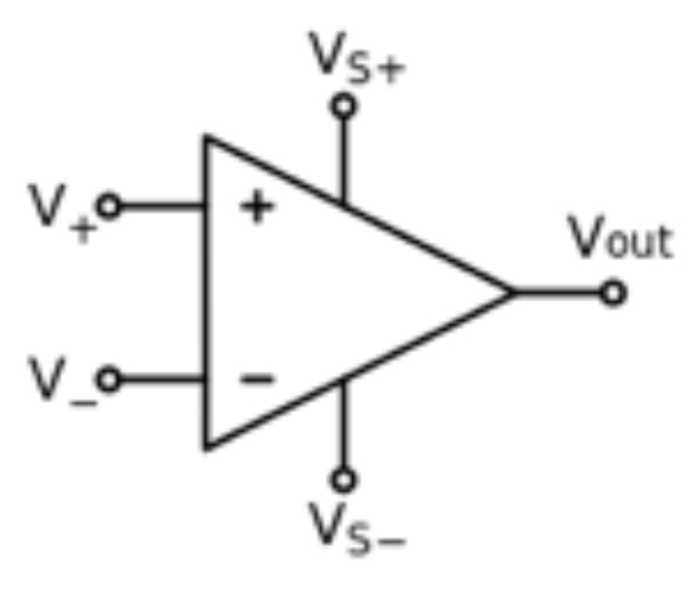
Op amps produce gain, and since you cannot get more energy out than you put in, it’s somewhat misleading that an op amp symbol in circuit diagrams is often shown without supply voltage leads. An op amp, however, cannot amplify a signal without adding energy, so supply voltage leads to an op amp symbol, if missing, are implied. If present, they are typically denoted as V+ and V-, although some op amps are “single supply,” which simply means that the second supply is created for you (using one voltage supply lead) inside the chip package.
Basic Operation of an Op Amp
Signals are fed into the two input leads of an op amp. Every op amp is “determined” to keep the input signals the same, but can only do so by driving its output in response, therefore the output of an op amp must be connected in a feedback loop in order for the op amp to accomplish its goal of maintaining a zero difference between the two input signals. In other words, the output of the op amp, connected as feedback (either fully or partially by using a resistor), acts to make adjustments to the input, as the op amp tries to balance the input signals.
There are two basic “rules” to remember when working with op amps:
- Theoretically, no current flows in or out of the input leads. It’s easiest to work with op amps if you accept this concept and go with it in your analysis. Assume infinite impedance at those inputs.
- An op amp will try to keep its inputs at the same voltage (using feedback.)
Building an Op Amp with Discrete Components
You can create an op amp as a circuit with discrete components, although most op amps are integrated circuits with carefully matched components for optimal performance, and matched components introduce less error. But if you were to make an op amp with your own components, you would technically have a very high gain, dc-coupled differential amplifier circuit with a single output. DC-coupling means that the op amp will pass both AC and DC signals.
Op Amps and Feedback
Op amp chips may or may not include a means to attach an external feedback loop, depending on what function it’s configured to do, but if external feedback is not available it is likely configured at a set value in the integrated chip. External feedback allows the designer to adjust it as needed, adding great versatility to the op amp’s long list of attributes. An op amp without feedback is impractical, and the ability to adjust the amount and direction of the feedback is what makes op amps so useful in the first place. (Feedback is when you take the output and connect it to one of the inputs on the op amp, so the op amp has information on how well it’s controlling the difference between the two inputs.) If you connect the op amp’s output to the non-inverting input (+), it is called “positive feedback.” If you direct the output to the other (inverting) input (-), you have “negative feedback.” With no feedback at all, an op amp is going to try and amplify as much as it can, given the supply voltage. It cannot amplify a signal to greater than the supply voltage.
What are “rails”?
The positive and negative supply voltages in op amp lingo are often called “rails” because the output signal cannot put out more energy than is being put in to the op amp. (To do so would be to break the laws of physics as we know it. Any op amp datasheet that claims to “go beyond the rails” is simply demonstrating inventive concepts in marketing or some additional means of adding energy into the equation.) Thus, the output signal of an op amp will always be bounded by its supply voltage “rails,” which are actually very slightly less than the supply voltages themselves, as the op amp wastes (e.g., via heat) and uses some energy in operation.
An op amp with no feedback will drive its output to the rails in an attempt to maintain zero difference between the inputs, an effect known as “saturation.” In any situation with no feedback, you would also call this an “open loop,” which is used in certain control systems, but rarely at the electronics level with op amps. Op amps can be sold as individual components which look a bit like tin cans with legs or as multiple op amps in a single IC package with pins. Op amps, as a building blocks in other, more complex circuits, are embedded in IC packages on printed circuit boards in nearly every product that uses analog signals. That is how useful op amps are to implementing analog applications. For instance, this would include the phone you might be reading this on, because the human voice is an analog input and op amps are used in a multitude of analog functions, or applications.
Related resources:
FAQ: What is Feedback?
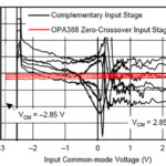
Understanding OpAmp input stages