Free-space optical links provide a reliable, cost-effective, and quick way to link two fixed communication nodes located a few kilometers apart.
When engineers think of “optical data links” or “optical communications” they almost invariably think of light (visible or not) in an optical fiber carrying data at high rates for tens or even thousands of kilometers. Alternatively, they may think of a simple low-performance optical link such as the infrared one of a TV’s remote control, or one over a very short distance of a few millimeters in an optocoupler used to provide galvanic (ohmic) isolation between two circuits, or perhaps a Li-Fi link in a room supporting semi-mobile “wireless” Internet connectivity at megabit or gigabit/sec rates.
But there’s another kind of optical data link in widespread use: the free-space optical (FSO) link, sometimes referred to as free-space communications. This article will look at the principles behind this type of high-speed data link, technical issues which affect FSO performance, and some commercially available FSO units that are in use. Many FSO installations are “low profile” either by installer’s preference or their physical setting, and you may have passed under one or used one without even knowing it.
Q: What is an FSO link?
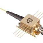
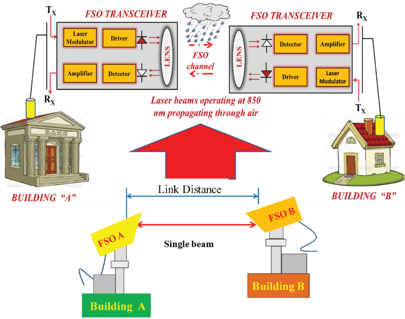
A: It’s a laser-based, fixed-in-place optical link between two nodes (Figure 1). This full-duplex point-to-point link transmits data through the air as light pulses, over a distance of up to about ten kilometers (but often less) and achieves data rates of about 100 Mbps to several Gbps. Typical availability is 99.99% or better despite interference from the occasional bird, fog, rain, and other possible path degradations.
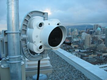
Q: Where are the node units placed?
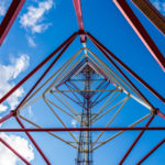
A: The transmitter and receiver nodes, usually joined in a single weatherproof enclosure, are mounted on rooftops, building sides, or available towers (Figure 2). This is a line-of-sight arrangement, so higher mounting yields more distance, but the practice is primarily limited by laser output power and other factors other than height. However, more height also means less likelihood of path blockage due to the growth of trees over the years and other obstacles that may arise in the future (new buildings, for example).
Q: What is connected to each optical transmitter/receiver node?
A: Usually, but not always, optic-fiber links are used to convey user data to and from the optical nodes. The users may be offices, campuses, and even residences. Coaxial cable is sometimes used in place of the local fiber-optic connection. A FSO system is fairly close to “plug and play.”
Q: Is this link solely between two points?
A: Yes, but a single site can support multiple units and link to multiple connecting points (Figure 3).

Q: Is the term “free space” the FSO type of link that NASA is testing between Earth and the moon, orbiting satellites, and even deep-space probes for higher data rates than RF links offer?
A: Yes and no. The term “free space” does cause some confusion, and the underlying principle is the same. However, the challenges are far greater with the non-terrestrial links for many reasons. A better name for Earth-only FSO links – and which is sometimes used – is “terrestrial free-space optical links.” The issues of communicating between Earth and anything at the distances of space, even to the nearby moon, and in a scenario where everything is moving, are orders of magnitude more difficult than fixed-in-place terrestrial links.
Q: Are these free-space links limited only to ground-based stations?
A: Not necessarily. The US Navy is also looking to use lasers on highly sophisticated stabilized platforms to communicate between ships and low-Earth orbit satellites (LEO). Still, again, it’s a very different situation compared to linking two stations a few kilometers apart and fixed in place.
Q: Why even consider such a system when you can get a microwave radio or optical-fiber-based links?
A: There are many reasons:
- As with all RF links, the microwave link requires spectrum allocation and regulatory permits, while optical links are license-free and have no spectrum regulation.
- The optical link supports much greater bandwidth and thus data rates than conventional microwave links.
- The optical link is immune to potential RF interference, nor is it affected by nearby optical links; in this respect, it is as “protected” as a shielded coaxial cable or optical fiber.
- It is nearly impossible to intercept or eavesdrop on the signal, and if you do, the users will likely see the drop in signal strength.
- The primary regulatory concern is safety and localized optical power, unlike the complex spectrum and power issues with which RF signals must contend.
Q: Are there other factors which make an FSO link attractive?
A: Not at all, there are more:
- The line-of-sight, free-space optical link is an attractive alternative when you need communications in temporary situations, such as a natural disaster; to get around ruptured or blocked paths; or to connect an array of TV cameras back to a control van at a sporting event convention, demonstration, or open-air concert.
- Setup only takes a few hours, and you can even rent the system by the day, week, or month.
- While an optical fiber could be used in some of these cases, installing one over even a short distance between two campuses requires special permits, digging trenches, backfilling, and restoration of the surface, along with many other time-consuming and costly headaches.
- It’s even a quick and effective permanent connection between two buildings in a crowded urban area or around campus, or from a localized receiver node to an apartment or office campus, all situations where routing the fiber is difficult, expensive, and may attract unwanted attention.
Q: Is doing an FSO link technically easy?
A: It’s not a challenge to set up an LED or a laser diode a few centimeters away from its corresponding photodetector and to transmit data successfully at high rates. It’s much harder to make this setup work when dealing with distance, laser-emitter safety issues, establishing the initial aim, maintaining that aim’s alignment, and functioning despite optical-path issues.
Part 2 of this article explores some of the practical implementation issues associated with FSO links.
Related EE World Content
Is Li-Fi “To Be” or “Not To Be”? Part 3 – Status
Calgary signs on for Terabeam FSO gear
LightPointe receives FSO patent
References
- Wikipedia, “Free-space optical communication”
- Science Direct, “Free-Space Optical Communication”
- IEEE, “A Survey of Free Space Optics (FSO) Communication Systems, Links, and Networks”
- Stanford University, “Free-Space Optical Communications — References”
- Purdue University, “Designing A Free-Space Optical/Wireless Link”
- Macom, “Free-space Optical Communication”
- Intech Open, “Free Space Optical Communications — Theory and Practices”
- European Scientific Journal, “Free Space Optical Communications: An Overview”
- RTU/Kota, “Seminar Report on Free Space optic”
- Arvix, “Free Space Optical Communication: Challenges and Mitigation Techniques”
- Military & Aerospace Electronics, “Navy looks for companies able to build optical communications between aircraft and submarines”
- Proceedings of SPIE “Research in Free Space Optical Data Transfer at the U. S. Naval Research Laboratory”
- StartUs Insights, “4 Top Free Space Optics Startups Impacting The Telecom Industry”
- Light Reading, “Is It Finally Time for Free-Space Optics to Shine?”
- Canon, “Canobeam DT-150”
- Canon, “Canobeam”
- CommConnect, “Free Space Optics”
- Airlinx, “Canobeam’s Auto Tracking Feature”
- fSONA, “SONAbeam FSO Systems”
- FSona, “FSO Guide”