 Tips for preventing problems could fill a book, especially if every professor, technician, or engineer were to contribute tricks and tips that they have learned over the years. However, many will agree that an ounce of prevention is worth a pound of cure. Here, we present a few general tips that may seem obvious to the experienced but are nevertheless fundamental nuggets that can save a lot of headaches.
Many people do not strap in for electrostatic protection when working with ICs, circuits, development boards, and so forth. Whereas it seems as if nothing is happening, the experience is akin to (not) washing one’s hands. You cannot see germs, you may not feel electrostatic discharge (ESD), and it may not do harm to neglect it now and then. ESD, however, can damage devices such that specifications are “off,” and the device will get worse with time. It’s annoying to strap in, but it’s just good hygiene, and when something isn’t behaving correctly, you will know it wasn’t ESD.
Check your voltage supply or supplies to make sure they are within the specified limits of the devices you are powering. If a supply voltage is too high, it will degrade or otherwise damage your devices. If a supply voltage is too low, your devices will not operate properly, and it could make troubleshooting unnecessarily complicated. For example, if a power supply is above the recommended voltage for a rechargeable battery, the battery can lose life/capacity. This often happens when a laptop is charged by a power supply that is “close enough” but too high; with time, the battery will not be able to hold a charge for more than a few minutes.
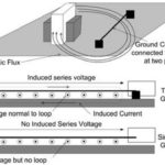
Grounding problems can be tricky, so it’s best just to start from the beginning with good grounding “hygiene,” if you will, especially with switching power supplies or if you have a lot of digital circuits. The topic of grounding can by itself fill an entire volume. It’s worthwhile to understand and follow good grounding practices. A good place to start is in understanding what ground loops are and how to avoid them, the benefits of an uninterrupted ground plane, and other PCB layout concerns.
Make sure solder joints are good. You can sometimes solve problems by reheating joints to ensure that cold solder joints, tin whiskers, or other issues aren’t the source of a problem, and re-soldering a joint is quick enough if you’re troubleshooting something on the bench. The same goes for troubleshooting equipment with grounding terminals screwed to the chassis; sometimes tightening a screw may be worth your time in the event you are troubleshooting a random problem.
Do not buy a cheap multimeter. With the flood of cheap goods entering the market every day, it might be tempting, but the multimeter is the bedrock of troubleshooting. Cheap multimeters can introduce error or inaccuracies; a cheap meter can have a low impedance and thereby introduce a resistance value into your circuit. It is well worth the extra money to buy a reputable multimeter. If you want confidence that your equipment is not counterfeit, buy from an authorized distributor.
When designing, always check circuits before proceeding to further design tasks. Validate your expectations of a circuit before complicating the picture with additional circuits, layers, or devices. Do not trust your intuition on how you think it will work, unless you are extremely familiar with the circuit and meticulously careful. Validating a circuit before moving on to the next stage is likely a standard practice for the experienced, but those new to design and implementation may be more trusting of computer modeling and theory than seasoned electronics veterans. Don’t be afraid to take notes.
Do not trust an auto-routing tool when you have analog circuits on your PCB. Always check PCB layouts for errors and introduced ground loops.
Component values can vary dramatically with temperature. Values on specifications will vary somewhat between devices, even within the same lot.
You may have some additional advice to share or add to the above. If so, feel free to comment so others can benefit from your experience.