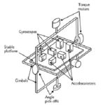
Part 1 of this FAQ examined the basics of IMUs based on spinning-rotor gyroscopes to establish and maintain a fixed attitude via a gimbaled platform, along with orthogonal accelerometers to sense motion along each axis. Part 2 looks at optical and MEMS-based gyros which have largely replaced the spinning-rotor core function except in the most-demanding situations.
Q: What are the drawbacks of the spinning-rotor IMU assembly?
A: In addition to the issues cited in Part 1, there is a mechanical weakness for which there is no easy solution: gimbal lock. If the three axes of the gimbal line up “just right,” the entire assembly with lock in a single position and not be rotate further, thus rendering the assembly useless. One way to avoid this is to deliberately “dither” the gimbal assembly to avoid this “all neutral” mode, but doing so adds to complexity and bring new issues.
Q: Are there non-mechanical alternatives to the spinning-rotor IMU?
A: Yes. In the 1960’s, the ring laser gyro (RLG) was developed, with a radically different approach to sensing changes in orientation.
Q: How does it work?
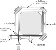
A; The RLG is based on the Sagnac effect, first observed by physicist Franz Harress in 1911 and recognized by Georges Sagnac in 1913; for various reasons, it is always referred to as the Sagnac effect. In this gyroscope, a single polarized beam of light is split by a half-silvered mirror into two beams, which are directed to travel in opposite directions around an optical path totaling several meters; mirrors are used at the corners to direct the beams, Figure 1. The entire optical path is enclosed in a vacuum so air molecules do not interfere with or scatter light even slightly.
Q: Then what happens?
A: When the counterrotating beams recombine at a detector placed coincident with their source, they interfere with each other and create a fringe pattern. The movement of these fringes is seen by an optical detector; the rate of fringe movement is a function of the rotational acceleration of the entire assembly around the RLG plane.
Q: What are the advantages of the RLG?
A: First, it has no moving parts, so it mechanically more reliable. Also, it has less warm-up time for the components to reach stable temperature. Though it has real-world sources of inaccuracy (as all systems do), it’s performance can be improved through various compensation and correction techniques, and by lengthening the optical path.
Q: Are those the major advantages?
A: Not at all, as there is one more that requires a major shift in system architecture. The biggest advantage of the RLG is that it is not a gimbaled system. Instead, it is a “strap-down” design, with each of the three orthogonal RLGs firmly attached to the vehicle. Instead of attempting to maintain a fixed-orientation of the platform in space as a spinning-rotor does, each RLG “goes with the flow” and reports on changes in attitude along its center axis.
The three change-in-attitude data sets must be processed to determine the final orientation change, but that is possible with analog circuitry or digital computation. Thus, the RLG not only eliminates the complexity of the gimbals, it removes them as a source of error and failure, as well as the possibility of gimbal lock.
Q: When did use of the RLG become widespread?
A: It was first demonstrated in the early 1960s, and by late 1970s, the RLG was standard on most commercial and military airplanes, replacing the gimbaled rotating-mass IMU.
Q: What happened next?
A: Although the RLG was a great success, it was relatively large and the optical elements had to be firmly mounted to withstand shock and vibration inherent in most applications, it also required an evacuated enclosure. However, the development of high-quality, low-loss optical fibers along with high-performance laser diodes as single-wavelength optical sources dramatically changed the RLG implementation and became the fiber optic gyro (FOG).
Q: How does the FOG implement the Sagnac effect and RLG principles?
A: The evacuated optical path with mirrors at the corners was replaced by a length of optical fiber. While basic accuracy and performance is initially dependent on the length of the optical path, the fiber – although many meters long – could be coiled into small size. Thus, the RLG with its physically long path became a FOG with an equivalent or even longer-length path but in a much smaller enclosure.
Q: What’s a representative FOG assembly look like?
A: It’s an all-electronic, no-moving part unit, and can be as small as a single-serving can of tuna fish to somewhat larger, depending on how much optical fiber is used, Figure 2.
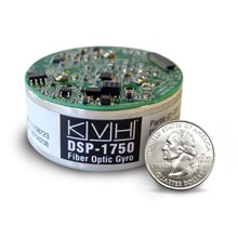
Fig 2: The fiber optic gyro uses the Sagnac effect as does the RLG, by replaces the evacuated optical path and its mirrors with a long, coiled optical fiber. (Image source: KVH Industries)
Q: Is the FOG the final word in IMUs?
A: It is for very high performance, almost as good as a top-end rotating-mass unit. But there’s much more to the story: in the past decade, a radically new approach to gyros has completely revolutionized the gyro and IMU world: the MEMS-based unit, using the same technology as used for silicon ICs and other MEMS devices.
Q: What are the primary attributes of a MEMS device?
Q: While not as accurate or precise as RLGs, they are amazingly good, small, light, low power, easy to use, and have other advantages. Without MEMS-based IMUs, we would not have applications such as consumer drones (some of which weigh around a pound). MEMS-based IMUs are often used in conjunction with GPS receivers for higher system-level performance as well as navigation and guidance redundancy and backup.
MEMS-based gyros were developed over the past decade to two decades, as an extension technology to the MEMS-based accelerometer. A MEMS unit is housed in a small IC package, uses a few mW of power, and cost a few dollars, each of which is a reduction of many orders of magnitude from any of the previous gyro designs. Note that they are also used in many non-IMU applications such as detection of imminent vehicle rollover.
Q: What is the principle of the MEMS gyro?
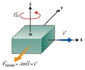
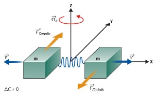
A: It is not based on rotating masses or counterrotating light beams. Instead, it adopts the Coriolis effect, Figure 3 (note, although often mislabeled, this is an effect and not a force!). When a mass m is moving in linear direction v and undergoes angular rotation Ω, the mass experiences a force F in the direction of the arrow, as a result of the Coriolis effect. The physical displacement which is caused by the Coriolis effect is capacitively sensed by an associated MEMS structure and circuitry.
Q: How is this actually implemented?
A: In the most-common configuration, silicon is etched to create a pair of tuning fork masses. These masses are stimulated by an applied oscillating electric field which causes them to also oscillate and move constantly in opposite directions, Figure 4. When angular velocity is applied, the Coriolis effect on each mass is also in opposite directions, which results in a change in the capacitance between them; this change is sensed. However, when the two masses undergo just linear acceleration, they move in the same direction, so there will be no change in capacitance between them.
Q: An IMU also needs accelerometers; how is this realized?
A: It is fairly straightforward, at least in principle, to build a MEMS device which includes a proof mass suspended by silicon springs, and then sense its motion and thus acceleration. MEMS-based accelerometers are now commonplace, low cost, and highly accurate. They ae now used extensively in systems including airbag deployment, rollover detection, and many other applications besides IMUs.
Q: What has been the result of the result of MEMS-based IMUs?
A: They have completely transformed the navigation and guidance world, making possible a wide range of applications which were previously simply not possible, or required large, costly, heavy, power-hungry, and hard-to-use subsystems. Now, a few dollars buys a “pretty darn good” IMU which requires only a few square millimeters and a few milliwatts.
References
- “Are We There Yet? Innovations That Led to Navigational Certainty”
- “Fiber-Optic Gyro Merges Optical Interference, Relativity to Define Motion and Location”
- “Spinning spheres test relativity’s subtlety” (Gravity-Probe B)
- Donald MacKenzie, “Inventing Accuracy: A Historical Sociology of Nuclear Missile Guidance,” MIT Press, 1990, ISBN: 9780262132589.
- Anthony Lawrence, “Modern Inertial Technology,” Springer, Second Edition, 1993, ISBN: 0-387-98507-7.
- “PIGA Accelerometer“
- http://www.draper.com/history
- “Introduction to MEMS gyroscopes”
- “A Survey on Ring Laser Gyroscope Technology”

