Model-based systems engineering (MBSE) supports requirements development, design, analysis, verification, and validation of complex systems, especially cyber-physical systems and systems of systems. Verification (simulation) and validation (testing) are key elements of MBSE. Model in the loop (MIL), software in the loop (SIL), processor in the loop (PIL), and hardware in the loop (HIL) simulation and testing take place at specific points during the MBSE process to ensure a robust and reliable result.
This FAQ looks at the origin of these testing and simulation activities in model based design (MBD) processes for large software projects, followed by a discussion of how each is implemented during MBSE and closes by considering how this methodology results in cost savings in addition to improved system design outcomes.
In MBSE, models are software representations of system elements such as electrical, electronic, mechanical, hydraulic, optical, etc. MBD leverages simulation to predict the operation software on a to-be-constructed physical system or system element.
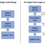
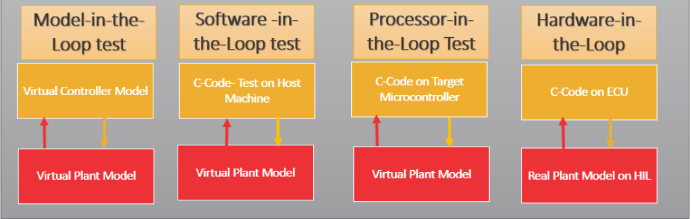
The term ‘in-the-loop’ originally referred to the software environment, the controlled system, or the hardware to be simulated. Today, it increasingly refers to the complete software and hardware models and physical system. The combined models of the various system elements comprise the digital twin of the ultimate system. MIL, SIL, PIL, and HIL simulation and testing are used sequentially to validate the results of the MBD process, often as part of an overall MBSE effort. If a simulation does not produce the desired result or requirements are modified, it can be necessary to go back to the previous MBD step until the required result is achieved. All four testing and simulation steps must be successfully completed prior to the start of system integration (Figure 1).
Model-in-the-Loop
MIL testing and simulation is the first point for software verification and validation. It consists of testing individual or integrated model modules in a development environment, such as ASCET from ETAS or MATLAB Simulink from Mathworks. For example, after a plant model has been developed, MIL is used to validate that the controller module can control the plant as desired. It verifies that the controller logic produces the required functionality.
Software-in-the-Loop
Following model verification, SIL generates code from the controller model and uses that code in place of the controller block. SIL testing consists of verifying the functionality of embedded software, algorithms, control loops, and other system elements on a personal computer or other platform without using the actual control hardware. It consists of simulating the software as C code and the plant as a software model. Suppose there are any anomalous results from SIL. In that case, it can be necessary to return to the MIL step, make adjustments as indicated by the SIL results, reconfirm that the adjustments still produce acceptable results from MIL testing, and then repeat the SIL verification process. In complex systems, it can be necessary to repeat this circular process several times. Once acceptable results are obtained for both MIL and SIL verification, the next step is PIL.
Processor-in-the-Loop
Depending on the system architecture, PIL can also be referred to as FIL (FPGA-in-the-loop) testing. In this step, the embedded software, algorithms, control loops, and other system elements are run as a closed-loop simulation on the actual processor (or FPGA) hardware instead of on a personal computer or other platform. This ensures that the hardware can run the controller software without glitching and that the outputs are as expected. Problems at this stage can identify a processor that may not be capable of performing the required tasks, or it can identify the need for software modifications. If software modifications are needed, it can be necessary to return to SIL or even MIL testing before returning to PIL.
In parallel with the development and validation of the control software using MIL, SIL, and PIL testing, the various hardware systems and subsystems are being modeled and validated using MBSE tools and techniques. Before beginning the system integration process, HIL testing is usually the final validation and verification step.
Hardware-in-the-Loop
HIL testing occurs before connecting the embedded processor to the actual hardware by running a simulated plant model on a real-time system such as Typhoon, OPAL-RT, dSPACE, Plexim’s RT Box, Speedgoat, and NI. Most of these tools work with simulation models created using platforms such as ASCET or MATLAB Simulink. HIL includes deterministic simulations and real physical connections to the embedded processor, such as analog inputs and outputs, communications interfaces, etc. It captures the real-time interaction between the control software and the actual hardware environment and can identify glitches and other problems that can elude detection in simulations. For example, delays and attenuations can be added to an analog channel that can cause instabilities in the control loop. HIL testing is required in automotive and aerospace applications, especially for safety-critical functions. As various subsystems are integrated, it may be necessary to return to HIL testing if a problem occurs. In extreme cases, it can be necessary to return to an even earlier stage in the MIL, SIL, and PIL process.
Importance of early and thorough design verification
MBE approaches can provide early design verification and speed the development process. MBSE, for example, is particularly valuable in numerous scenarios such as:
- Complex systems. Increasing functional complexity from generation to generation can exponentially complicate the design process, especially when new functionalities are added on top of an existing system, such as vehicles with more and more advanced driver assistance system (ADAS) functions that must work in harmony and share access to multiple electronic control units (ECUs).
- Stricter safety and performance requirements. Safety and performance expectations for aerospace systems, vehicles, and even Industry 4.0 cyber-physical systems are increasingly complex. MBSE tools support early-stage testing and simulations that can save time and expense while still meeting challenging performance and safety requirements.
- Cost and time to market. Better, faster, cheaper has been the mantra of the electronics industry for decades, and that same expectation now extends to complex systems. The use of MBD and MBSE enables faster development of increasingly complex cyber-physical systems and systems of systems, and that in turn supports better system performance and reduced costs.
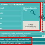
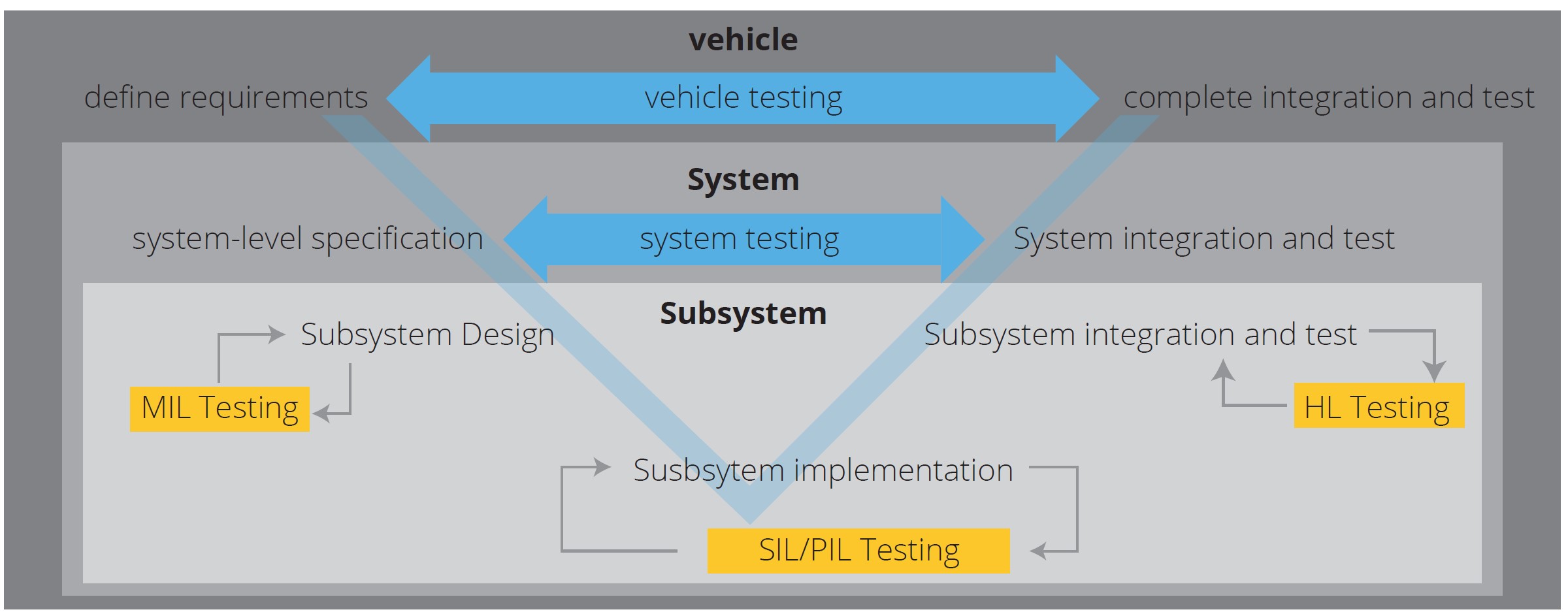
Using models in place of hardware prototypes in the design environment inherently reduces costs and increases flexibility. That can be especially important for the development of software prior to integration with actual hardware. Once the software models have been validated through the MIL, SIL, PIM, and HIL processes, hand coding is not necessary. The embedded code can be automatically generated, producing a more uniform code and software structure, and reducing the overall time needed to produce the final code. That benefit carries throughout the software development life cycle from the initial definition of requirements to the completed integration process and deployment (Figure 2).
More about HIL
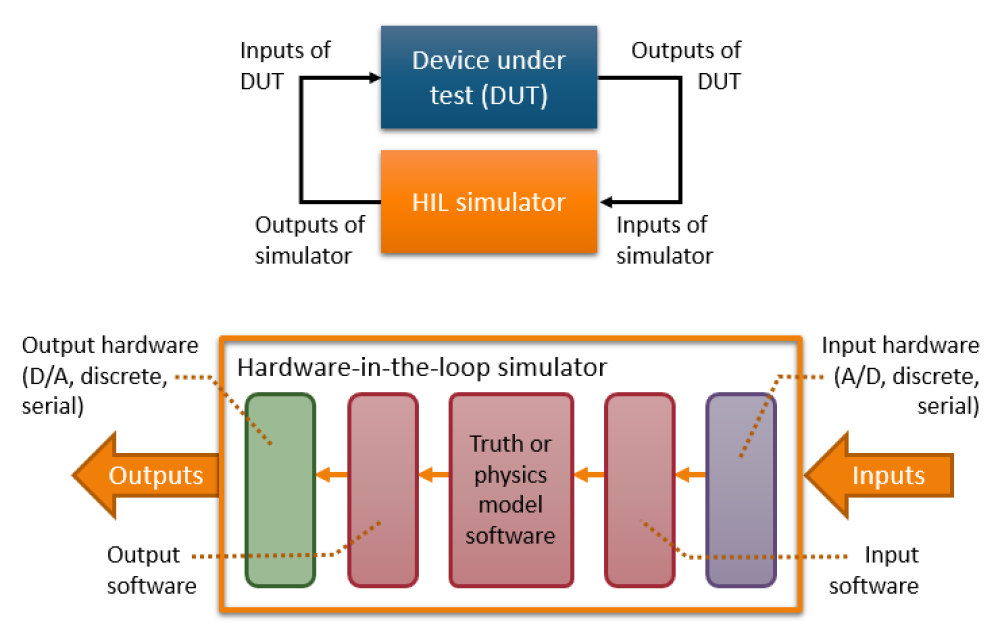
The use of HIL for software validation can be especially important for ensuring performance and reducing risk when the time comes for actual system integration. Testing new designs on vehicles or aircraft is fraught with challenges and expensive. A first approximation to address this challenge is using models in the loop (MIL). However, MIL testing and simulation are limited in their potential to identify higher-level system integration problems. HIL bridges that gap. For example, HIL enables the electronics controller design team to work collaboratively with the mechanical team when creating a new ECU. The concept of an ECU can extend from simple window opening/closing features to complex flight controllers. A sophisticated HIL controller enables the test engineer to intentionally inject problems such as faults or alarms into the test to find out how the ECU reacts (Figure 3). This can be especially important in safety-critical systems where some faults may be expected to occur only on very rare occasions.
Early defect discovery and cost savings
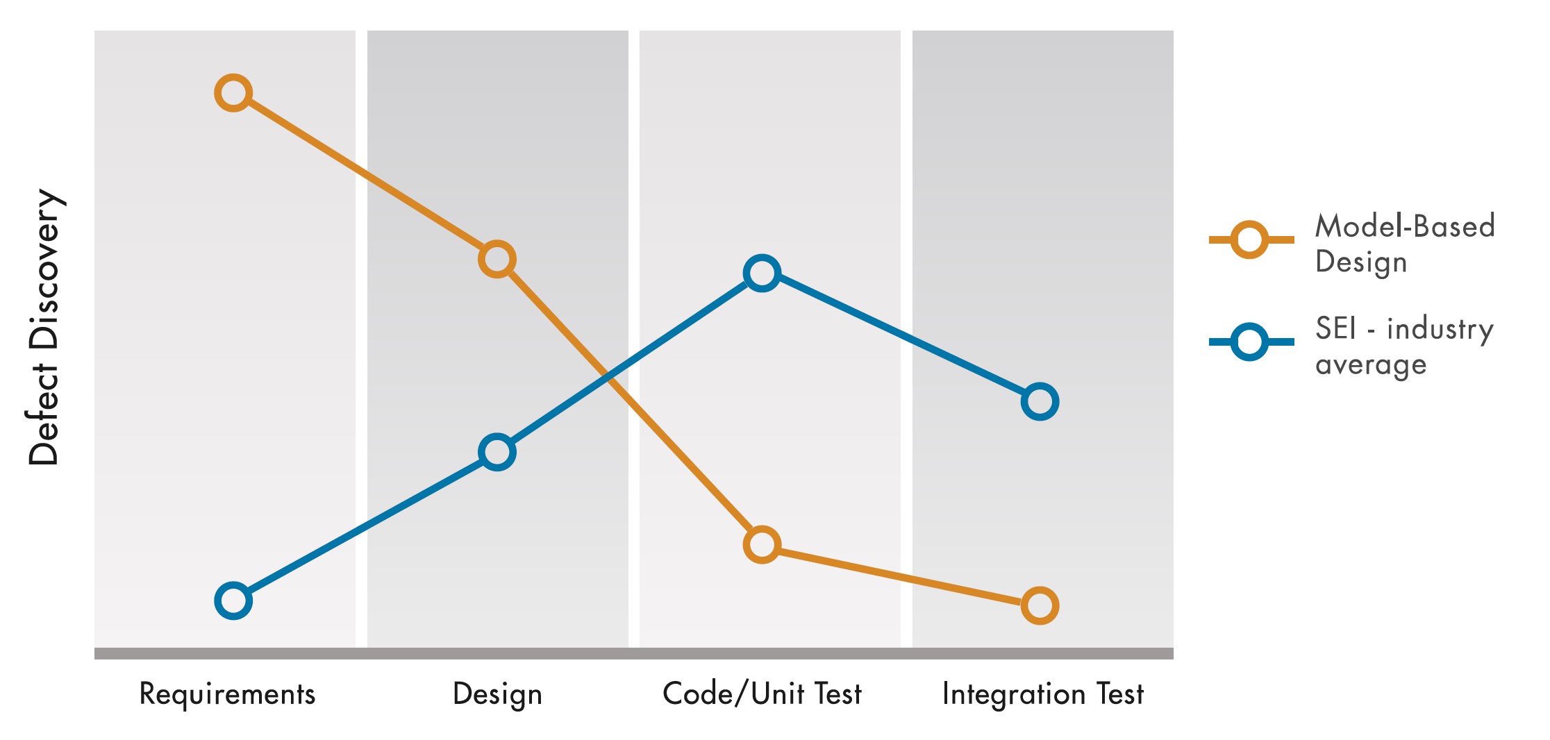
MBD and MBSE use models throughout the design process to reduce ambiguity in product functionalities and specifications and support simulations at every stage to verify and validate performance. The earlier use of models enables the examination of various solutions and possible system architectures. Using a common toolchain from conceptualization and development through the operational stages of the system lifecycle also enables greater collaboration between diverse design teams and faster design iterations. The faster development process produces cost savings since MBSE enables the discovery of model defects earlier than the traditional Software Engineering Institute (SEI) industry averages (Figure 4). Savings result from better requirements analysis plus continuous testing, validation, and verification.
Summary
MIL, SIL, PIL, and HIL testing and simulation were originally developed for use with large-scale software projects. Today, they are also combined with the other elements of MBSE for the creation of complex cyber-physical systems and systems of systems. There are numerous ways that the combination of MBD and MBSE contributes to reduced development times and improved system performance throughout the software and system life cycle.
References
Hardware-in-the-loop and MBSE, Siemens
Measuring the Return on Investment of Model-Based Design, MathWorks
Mission Engineering, Digital Engineering, MBSE, and the Like: The One Underlying Essential Attribute, Boeing
Model-Based Design and MIL to HIL, Algorithm
Model based systems engineering for accelerating software development, L&T Technology Services
What are MIL, SIL, PIL, and HIL, and how do they integrate with the Model-Based Design approach?, MathWorks
What is Hardware-in-the-Loop (HIL) Testing?, Genuen