Depending on the context, SDLC can stand for system development or software development lifecycle. In model base system engineering, the SDLC (sometimes called the Application Development Lifecycle, ADLC) is a multi-stage process for planning, creating, testing, and deploying a system, including requirement analysis, design, development and testing, implementation, documentation, and evaluation. Model lifecycle management (MLM) and levels of model maturity are also important to ensure that a MBSE modeling environment remains relevant and meaningful throughout the system’s lifecycle.
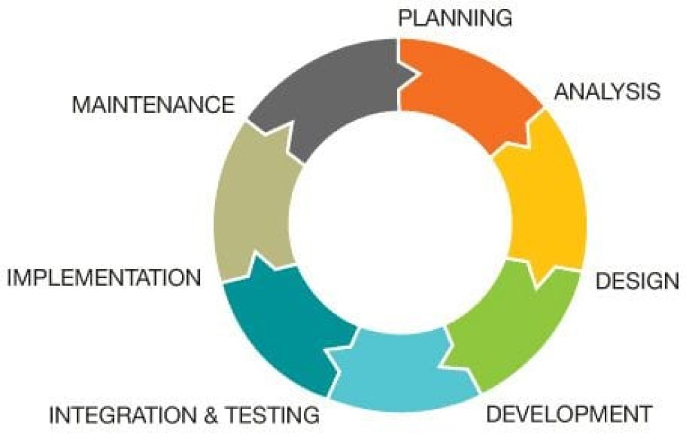
MBSE is a system engineering approach that emphasizes detailed modeling and simulations using a digital twin of the system under development and a digital thread to track all development activities and changes to the digital twin and the system for the entire SDLC. MBSE and SDLC are interrelated concepts. SDLC is a general step-by-step process that can be used with various systems engineering approaches, not just MBSE, and includes (Figure 1):
- Planning including determination of feasibility
- Analysis of system functional needs
- Design of the system architecture specification
- Development of the various system elements
- Integration, testing, and simulation, including detailed verification & validation (V&V)
- Implementation and production of the system
- Maintenance, including lifetime support for upgrades and decommissioning at end of life
The stages outlined above are not necessarily linear but can be implemented iteratively as the process unfolds, and additional information becomes available. Considered in more detail, these stages include:
Planning – The goal of planning is to arrive at a clear and comprehensive definition of the problem to be solved, system operational objectives, the operating environment, and other factors. It also includes a preliminary analysis of the development costs, required resources, timeline, and projected cost of the final system.
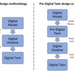
Analysis – Determination of specific functions needed to achieve the system operational objectives identified during planning. This can include market research in addition to inputs from various stakeholder groups working on the project to generate and prioritize functions. It can also include developing a pre-digital twin to identify potential design defects. Early identification of defects is a key benefit of using MBSE and SDLC and reduces overall costs and shortens time to market.
Design – Consideration, and comparison of various system architecture options. This includes how the various functionalities interrelate and interact, required user interfaces, and any interaction with systems outside of the primary system (e.g., cyber-physical systems and systems-of-systems)—the start of developing the actual digital twin and the associated digital thread. Plus, continued identification of possible defects.
Development – Including continuing refinements to the digital twin and initial development of specific physical design elements. This is a core activity in MBSE and SDLC. It generally includes ongoing simulations as well as development of physical prototypes. Identification of defects in the interoperability of system elements at this stage can speed up the next stage of integration and testing.
Integration and Testing – V&V of the operation of the integrated system, including satisfaction of industry standards, safety requirements, system robustness and resilience, and so on. This includes all hardware, software, and cyber system elements.
Implementation – Manufacturing, and delivery of the system. This can also include a unique digital twin for each system manufactured (related to serial numbers) to enable lifetime monitoring of operating environments, maintenance and repair requirements, upgrades, and so on.
Maintenance – Recording how the system is maintained after delivery to the end user, including lifetime support, upgrades, and decommissioning at end of life.
Model lifecycle management
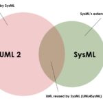
When using MBSE, MLM is just as important as SDLC. MLM includes all formal and well-defined models such as analysis and simulation models, architecture models, models created using SysML, architecture analysis and design language (AADL) models, and computer-aided design, computer aided-engineering and computer-aided manufacturing (CAD/CAE/CAM) models. MLM does not include informal sources such as text documents, drawings, slides, and so on, where the syntax and semantics are not well defined by a modeling language.
MBSE uses numerous models related to specific design functionalities, testing, and simulation models, as well as models related to manufacturing processes and other aspects of the system lifecycle. MLM tracks connections between the system architecture model (or model elements) and domain-specific models (or model elements). Those connections can be dynamic through time as the system evolves, and the scope of the system model may vary. At some points, it can be an abstract specification model of the system and its elements, and at other times, it may include detailed design elements and specifications.
Models can perform different functions, such as providing reference connections for basic traceability, data map connections for exchange of parameter values, and transform connections for generating and synchronizing structures and data between models. Model contents can include various documents for model construction, data and results files from model use, and model libraries and associated tools (Figure 2). MLM keeps track of all relevant models and related information throughout the system lifecycle.

Measuring model maturity
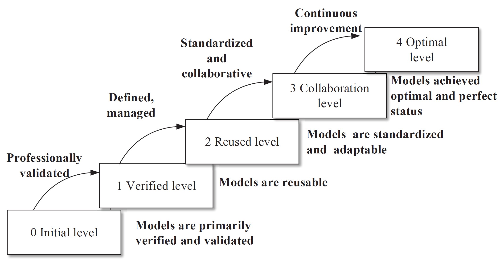
Models in MBSE are not static constructs; they are dynamic and can change throughout the SDLC. As a result, the concept of model maturity is an important consideration. Model maturity reflects the utility of the model. An immature model can lack standardization, be poorly documented or disordered and inefficient, include a high level of uncertainty related to simulation results, result in outright process failures, and is not reusable. A mature model has well-structured properties, is standardized and clearly defined, includes well-controlled processes that produce high-quality simulations, has no modeling errors or failures during model execution, and is easily reused. Model maturity can be referred to using five levels (Figure 3).
Level 0 – initial model. Beginning of model development process and the model is not verified or validated. Errors that result in failures of simulation with the model should be expected. There are many uncertainties related to the model’s utility, and it is not well documented or managed.
Level 1 – verified model. Model has preliminary verification from the model developer. Documentation is incomplete and not standardized. There are a few remaining uncertainties related to simulations performed using the model. There are few if any, management tools, and the model is mostly unmanaged.
Level 2 – reusable model. The modeling process is well organized with standardized and complete documentation. The model has been independently verified, validated, and accredited. There are no errors in the model that result in failures. User interfaces are easy to use, and the model can be reconfigured for other applications without degrading its performance. A basic model library has been added for model management.
Level 3 – collaboration model. Improved user interfaces that conform with the required interoperability standards. The model is reusable across heterogeneous environments. There are a few and minor problems during model use. Reconfiguration of the model has been simplified for use in different development efforts without any performance degradation. An engineering-level library environment is used to manage the model.
Level 4 – optimal model. The model is highly standardized. It has been verified, validated, and accredited by a professional service and has high fidelity and credibility. The interfaces of the model are user-friendly and adaptable to several interoperability standards. The model has strong adaptability to heterogeneous environments. There are no errors during model use and its highly adaptable across various environments. The model is maintained by professional management with a commercial-level model library and includes all needed supporting tools.
Summary
Lifecycle management is an important aspect of MBSE. It includes both SDLC and MLM for the system itself and for the models, respectively. SLDC and MLM are multi-stage processes that follow the system throughout development until the end of life and decommissioning. Model maturity is another important concept in MBSE. Models form the foundation of MBSE, and having a model with the correct level of maturity is a necessary condition to ensure an efficient and productive system engineering effort.
References
Model Lifecycle Management for MBSE, omgwiki
Model Maturity Towards Modeling and Simulation, International Journal of Modeling, Simulation, and Scientific Computing
Systems development life cycle, Wikipedia
System Development Life Cycle: Basics to Know, Intellectsoft