Simulation process and data management (SPDM) is a software tool that manages simulation processes and data across the enterprise and the product lifecycle. In MBSE, SPDM can be used to help build and maintain the digital thread. SPDM provides traceability. It’s related to product lifecycle management (PLM). PLM provides a database for all information related to a physical product and provides a communication framework between product marketing, engineering, manufacturing, and field service. SPDM focuses on simulation processes, and PLM focuses on product-related information.
This FAQ begins with an overview of SPDM and how it supports and helps to build the digital thread in the MBSE process, reviews some challenges when using SPDM, looks at how PLM is structured, and some PLM standards, and how SPDM can be implemented within PLM and closes with a brief look at how SPDM and PLM relate to digital twins and digital shadows.
As a strand of a digital thread, SPDM provides a framework for managing simulation data configurations and a platform for collaboration among diverse constituencies. It provides traceability of simulation-related data and supports a single repository of information used for optimizing product designs and as part of the overall PLM process.
PLM manages product-related information, such as the bill of materials (BOM), throughout the product lifecycle. It often begins with an ‘as designed’ BOM, which can morph onto an ‘as manufactured’ BOM when the product or system is optimized for production, and further evolve into ‘as sold’ and ‘as maintained’ BOMs to reflect any customization or serialization, and all maintenance or modifications, respectively.
Together, these strands of simulation data and product BOM data form key parts of a digital thread. Other strands in the digital thread relate to digital modeling, development of specifications and features, design-specific activities, and so on. The complete digital thread provides comprehensive lifecycle traceability that links all elements of a digital twin with the physical product it represents, sometimes down to the serial numbers of individual embodiments.
For example, if there is a requirement to improve some aspect of a system or product performance after it has entered production, SPDM and PLM can provide important insights and support. They can link simulation data with current BOM changes and help engineering and production develop the improved solution in a rapid and coordinated manner. Without the data provided by SPDM and PLM, that process can be overly iterative and cumbersome. SPDM enables the reuse of simulation processes and data and the identification of best practices at each stage of the product lifecycle.
SPDM challenges
Simulation processes are often multidisciplinary in nature, making them inherently challenging to track and manage. Some of those challenges include:
- Simulation and data complexity – A typical design process can require multiple simulations to arrive at the desired result. SPDM is required to track each iteration and its results which can create massive databases that must be managed.
- Data traceability – Simulations in MBSE can occur across multiple engineering domains complicating data traceability and maintenance of the digital twin as the ‘single (and complete) source of truth.’
- Maintaining simulation templates – MBSE design teams often work from diverse locations making the maintenance of a common repository of simulation templates an important activity to ensure efficient collaboration.
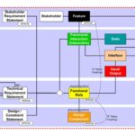
- Multiple uses of simulation and simulation data – In MBSE, models are often created within simulations to link the digital world with the physical world. On the other side, simulations can represent physical prototypes and link the physical world to the digital world (Figure 1).
- Efficient decision making – Simulation data needs to be consumable by a range of business and design functions and must be presented in formats relevant to each group.

PLM standards and elements
A key feature of SPDM and MBSE is the replacement of physical documentation with digital databases. To fit into that digital context, the essential elements of PLM must evolve to include:
- Manage design and process documents in digital formats
- Construct and control digital BOM records and track changes
- Include standard and custom part and document metadata for individual constituencies
- Manage materials content for environmental compliance
- Provide workflow and process management for all change approvals
- Control and maintain multiple levels of secured access, including the use of ‘electronic signatures’
- Provide links to connect with the wider world, such as enterprise resource planning (ERP) systems
As a result of the multidimensional nature and complexity of using PLM in MBSE, numerous organizations and agencies have developed a diverse range of PLM-related standards. Some organizations include; ANSI, ASME, EIA, GEIA, IEC, IEEE, IPC, ISO, and UL.
Using SPDM in PLM
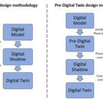
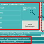
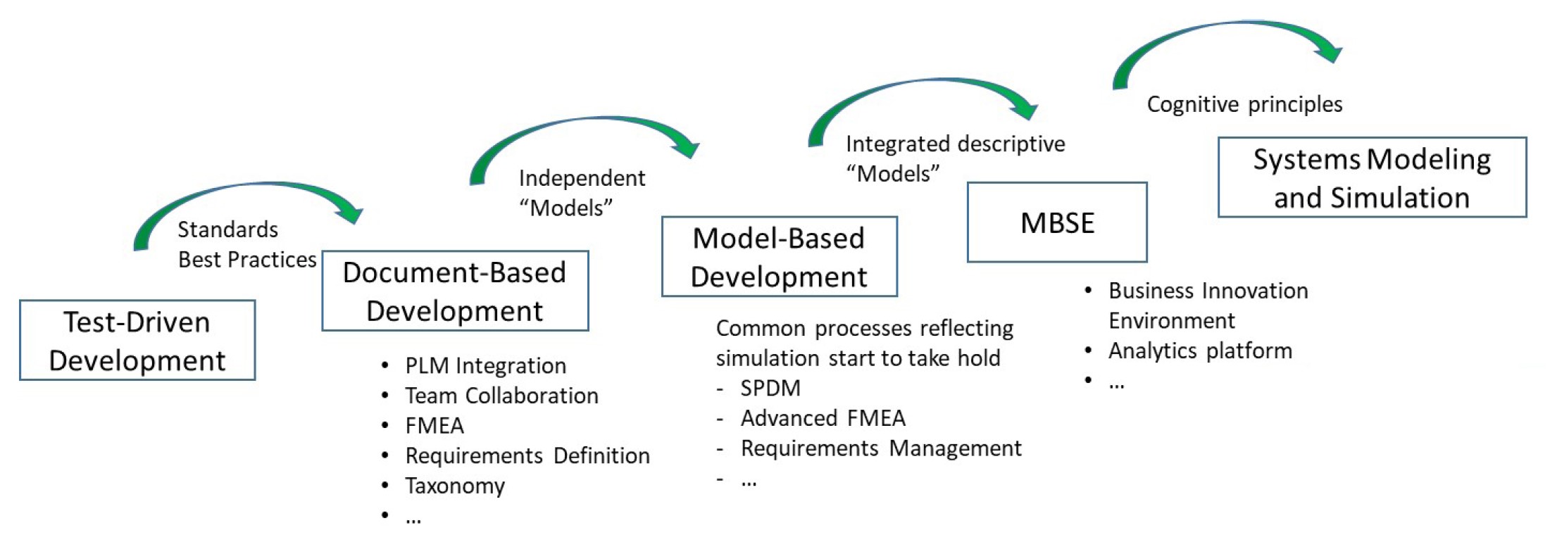
The integration of SPDM and PLM into MBSE does not occur overnight. It’s a process that involves several steps. Document-based PLM predates the development of SPDM and MBSE (Figure 2). Early PLM implementations were based on test-driven product development. Model base development (MBD) was the first time that simulation became deeply integrated into the development process. However, MBD is a more limited concept than MBSE and does not include the concepts of a digital twin or a digital thread. In addition, simulations within MBSE can be much more comprehensive and have multiple technology and physical domains at once. As the sophistication and complexity of systems modeling and simulation increases, the need for SPDM and PLM also increases.
Compared with yesterday’s ‘siloed’ systems development teams, the use of integrated PLM and SPDM approaches present several demands and challenges:
- Heterogeneous data – A single toolset is not generally capable of managing all the aspects of PLM and SPDM integration. Simulation often requires using multi-domain and multi-physics tools from different vendors, resulting in heterogenous data that needs to be efficiently managed in an SPDM and PLM environment.
- Metadata structures – Different teams involved in the product development process, such as marketing, various design engineering disciplines, software developers, and manufacturing, need to have the ability to create metadata structures that support their specific data consumption needs.
- Flexibility – Mountains of simulation data are not useful if the underlying SPDM processes lack the flexibility to efficiently integrate the data into the design process and help the teams move away from less desirable solutions and toward better outcomes.
- Agility – System design and simulation are inherently complex processes. SPDM tools need to help minimize the use of iterative and incremental development with more agile approaches that can speed time to market.
SPDM, PLM, digitals twins, and shadows
When fully integrated into MBSE, SPDM becomes part of the digital twin and the corresponding digital thread, and PLM is more related to digital shadows:
- A digital twin is a real-time and comprehensive virtual representation of a physical system or device that can be used for various purposes, including virtual simulations, integration, testing, monitoring, and maintenance. The digital thread provides complete documentation of the development of the digital twin and system development over the entire product life cycle and links the digital and physical worlds.
- A digital shadow is a software tool that integrates selected system-related data, called condition data, from different sources and is designed to support specific decision-making needs. Digital shadows are often created ad-hoc for one-off applications and are not necessarily designed for aggregation or reuse.
Various sources of condition data, as well as comprehensive virtual system data, are managed separately within the framework of the digital twin. The overall framework includes the digital twin, sometimes referred to as the digital master (DM), where virtual simulations take place, and simulation process data management in the digital twin (SDM-DT), which can provide a link between the digital shadow and the digital twin (Figure 3). A product data connecting model is used in MBSE, linking the product model and domain-specific simulation models and the condition data.

Summary
SPDM and PLM are important aspects of the complete MBSE environment. MBSE relies on extensive virtual simulations based on the digital twin. SPDM provides the tools needed to make the simulation data accessible in relevant formats to diverse users. PLM provides a link to the physical world, including management of the evolving product BOM and integration into wider ERP systems. As a result, SPDM is tightly coupled with the digital twin and the digital thread, while PLM is more closely related to digital shadows.
References
How Simulation Process and Data Management (SPDM) technology can ease simulation-driven development, ESTECO SpA
Product Lifecycle Management, Product Lifecycle Management
Selected PLM-related industry standards, Product Lifecycle Management
Simplifying Model-Based Systems Engineering, SMS_ThinkTank
Simulation Data Management in the Digital Twin, ScienceDirect
Why Simulation Data Management is Vital for Product Lifecycle Management, Tata Consultancy
Why Simulation Process and Data Management (SPDM) is a must for a successful implementation of MBSE and the Digital Twin?, Siemens