Current mirrors are common circuits but are mostly invisible, except to designers of analog or mixed-signal integrated circuits who can use large numbers of current mirrors on a single chip. A current mirror copies a current through one active device (such as a BJT or MOSFET) by controlling the current in another active device. If the input current is constant, the ‘copied’ current is also constant, regardless of loading. In some instances, the input current can be a varying signal, in which case the ‘copied’ current has the same variable characteristics.
This FAQ reviews several common current mirror topologies and where they are used.
Current mirrors have high output impedance to help keep the output current constant regardless of loading and low input impedance to keep the input current constant irrespective of the drive. They can be implemented as an inverting current amplifier or as a current-controlled current source (CCCS). The primary current mirror specifications include:
- Output current magnitude for current sources
- Transfer ratio for current amplifiers.
- AC output resistance governs how much the output current varies with respect to the voltage changes.
- Compliance voltage range starts with the minimum voltage drop across the current mirror output to ensure proper operation (the compliance voltage) and ends at the upper voltage where the mirror goes out of specification.
Current mirror operation can be susceptible to changes in the biasing voltage, changes in temperature, as well as transistor matching, layout considerations, and other factors.
A primary use of current mirrors is biasing amplifiers in integrated circuits. A single IC can include large numbers of amplifiers, and to bias, all the amplifiers to exactly the same level can be challenging. To overcome this problem, a single stable current source is implemented in the IC, and multiple copies of the stable source are generated using current mirror techniques.
Simple BJT current mirror
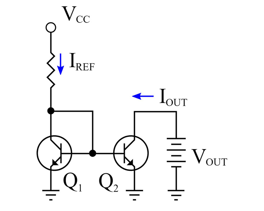
In a basic BJT current mirror, the input transistor operates as an exponential voltage-to-current converter when a voltage applied to the BJT base-emitter junction acts as an input quantity, and the collector current is used as the output quantity. Connecting the base and collector results in negative feedback, and the transistor acts as an opposite voltage-to-current converter. It controls the output base-emitter voltage to pass the collector current. A simple current mirror consisting of two cascaded transistor stages acting as reversed and direct volage-to-current converters, respectively, implements this approach (Figure 1). The emitter of Q1 is connected to ground, and the collector-base voltage is zero. The voltage drop across Q1 is VBE, and Q1 sets VBE for Q2. If the transistors are matched and the mirror output voltage selected, so Q2 has a collector-base voltage of zero, then the VBE of Q1 causes the emitter current in Q2 to be the same as the emitter current in Q1.
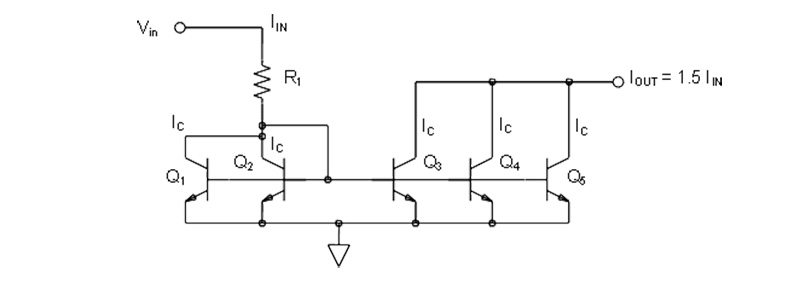
When using matched transistors, the input current to output current ratio (gain) is one, and the currents are equal. There are instances where a gain other than one is desirable. When fabricating current mirrors in ICs, it’s possible to control transistor characteristics as needed to produce specific gains. But, even in those cases, it’s easier to use matched transistors and modify the current mirror circuit to produce gains other than one. Arbitrary gains can be achieved by using various numbers of matched transistors on the input and output sides. For example, if there are N-matched transistors on the input side and M-matched transistors on the output, the gain of the current mirror will be M/N. For instance, in a current mirror with two matched transistors on the input and three on the output, the mirror gain will be 3/2, or 1.5 (Figure 2). All five transistors have the same VBE, and their collector currents, IC, will be equal.
Wilson current mirror
A Wilson current mirror is an improved configuration that provides a more constant current source or sink and a much more accurate input to output current gain. A Wilson current mirror can be implemented as a basic three-transistor configuration or an improved four-transistor configuration (Figure 3). Both are true, current mirrors, and the mirrored output current is a precise copy of the input current. The fourth transistor in the improved configuration lowers the collector voltage of Q1 by VBE of Q4 equalizing the collector voltages of Q1 and Q2. Forcing the collector voltages of Q1 and Q2 equalizes the performance degradation at high current on the input and output branches. That symmetry extends the linear operating range of the mirror. In addition, equalizing the collector voltages equalizes the power dissipation in the two transistors, reducing the potential mismatch from temperature effects on VBE.
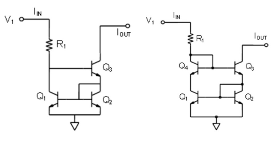
The major improvement in the Wilson current mirror is reducing the dependency on transistor beta values, making it less dependent on using exactly matched transistors. Another advantage of both the Wilson and improved Wilson current mirrors is that they have higher output impedances which improves current mirror efficiency.
Current mirrors with FETs
Current mirrors can also be implemented with MOSFETs. For example, in the basic current mirror, the two MOSFETS (M1 and M2) operate in saturation or active mode, and IOUT is directly related to IREF (Figure 4). This mirror operates based on the fact that a MOSFET’s drain current (ID) is a function of the drain-source and the drain-gate voltages, VDS and VDG, respectively. For M1, ID = IREF. With VDG = 0 for M1, IREF determines the value of VGS. Both MOSFETs have the same VGS; therefore VOUT is equal to IREF when VDG for M2 = 0. Of course, this all depends on the MOSFETs being matched with the same channel dimensions, threshold voltage, and so on, resulting in them having the same ID function relative to VDG and VGS.

Advantages and limitations
In addition to the basic configurations reviewed above, current mirrors can be implemented with cascoded structures, using an internal error amplifier in a gain-boosted, or feedback-assisted, current mirror for an improved cascode structure, emitter followers to reduce the mismatch from the base current, and using resistor degeneration to increase the output impedance and reduce the static error. Widlar current source is a basic two-transistor current mirror that adds a degeneration resistor on the emitter of the output transistor, enabling the current source to generate low currents using only moderate resistor values. Common limitations of most current mirrors include:
- They can add noise. Adding large emitter resistors can reduce the noise to a manageable level.
- They can add distortion. Unfortunately, the use of emitter resistors can aggravate this condition if the VBE of the transistors is not well matched. The added distortion can be mitigated using emitter resistors much larger than the dynamic emitter impedance of the transistors or using very closely matched transistors.
Specific advantages of the Wilson current mirror include:
- It does not use large area resistors or need additional bias voltages
- Low static error. Small and random device mismatches mostly cause the input/output current error.
- The improved Wilson current mirror has extended linearity and can operate at higher currents.
Wilson current mirror disadvantages include:
- The minimum voltages from the common rail to the input or output needed for proper operation are higher than in the basic two-transistor current mirror, reducing the headroom to generate the input current and limiting the output compliance.
- Feedback raises the output impedance and contributes to collector current fluctuation noise on the output.
- All three transistors can add noise to the output.
- It’s impossible to produce multiple current sources using a Wilson current mirror from a single input reference current.
Summary
Current mirrors are common but mostly hidden circuits. They are important in the design of mixed-signal and analog integrated circuits and can be designed for 1:1 input-to-output current ratios or arbitrary ratios as required. Current mirrors can also be designed to provide multiple current sources from a single input reference source. The basic two-transistor topology can be modified to provide improvements in various performance factors. The Wilson current mirror is the simplest way to deliver improved current mirror performance. However, it cannot be used to provide multiple current mirror outputs.
References
Current mirror, Wikipedia
Low-Voltage Wilson Current Mirrors in CMOS, Orlin College
The Current Mirror, Analog Devices