The object-oriented systems engineering method (OOSEM), sometimes referred to as object-oriented systems engineering (OOSE), is a systems-level development method from the Object Management Group (OMG) that combines object-oriented concepts with traditional systems engineering practices. It leverages concepts originally used in object-oriented software development and applies them to systems engineering.
This FAQ starts with a review of basic OOSEM concepts. It compares OOSEM with traditional structured analysis approaches to model-based systems engineering (MBSE), looks at how OOSEM is implemented and the key features of an object-oriented methodology, and closes with a look at how the International Council on Systems Engineering (INCOSE) views OOSEM.
MBSE can be implemented using a variety of modeling languages. These languages can be differentiated in several ways, such as:
- Is the information expressed using visual or textual formats?
- Are the paradigms used to group the information based on object-oriented, functional, or other considerations?
Visual languages are often used for modeling since they are easily readable by diverse stakeholders. Object-oriented languages are favored in systems engineering because they can be easily applied to systems that can be decomposed into sets of objects. The resulting model includes functions for needs and requirements analysis, logical and allocated architecture design, and validation and verification. The Unified Modeling Language (UML), and Systems Modeling Language (SysML), both from OMG, can be used for OOSEM. Initial OOSEM implementations relied on UML; SysML is more commonly used today.
UML was developed for software engineering, and SysML is an adaption of UML optimized for use in MBSE. SysML is a graphical language that uses diagrams and tables to express system information and provide a framework for representing system structure, behavior, and requirements. Before OOSEM was available, systems engineering relied on the structured analysis to analyze needs, identify features, and develop a system model. Like structured analysis, OOSEM is used to define a system model, but it takes a fundamentally different approach.
The structured approach begins with a functional analysis where functions are defined as data transformations that operate on data inputs to produce required outputs. Once the required system behavior has been sufficiently decomposed and specified, the functions are further defined as system elements or components, and physical modeling of the system can begin. The classic ‘V diagram’ is often used to visualize the structured analysis approach to MBSE.
Like the structured approach, OOSEM is iterative. OOSEM begins with analyzing objects that make up the system architecture, then moves to allocate the functions to the objects to fulfill specific needs. During subsequent design iterations in OOSEM, each object is further decomposed into sub-components to perform sub-functions. The cycle is repeated until the system functionality is sufficiently granular to enable requirements development that will lead to the system specification (Figure 1).

Four OOSEM features
As used in MBSE, OOSEM combines concepts such as data flows from structured analysis with object-oriented concepts. It also uses various modeling techniques, including logical decomposition, partitioning criteria, causal analysis, and variant design, to deal with a spectrum of concerns throughout the system life cycle. OOSEM begins with separating concerns to manage complexity, followed by integrating concerns to produce a cohesive system model. There are four key features of OOSEM as it’s applied in MBSE:
Abstraction enables designers to separate the functionality of a component from its physical implementation. Using logical representations of components can identify functionality and component attributes common across the system. Removal of the constraints inherent in physical representations enables a better understanding of component functionality and how various components interface with each other on a logical level.
Encapsulation identifies the boundaries of objects and their interface with other system elements. Functions are encapsulated inside the object and not made visible to other components. Various components interact using the defined interfaces, independent of the internal functions. Encapsulation enables the replacement of components with other components that have the same functional outputs and the same interfaces. It supports modularity and reduces or eliminates any interdependency between components.
Inheritance can enable one component to inherit all the functionality and interfaces of another component. It’s not limited to objects and functions. Inheritance is used in OOSEM when creating a representation of a physical component. A newly created physical component can inherit the properties of an existing logical component. The designer can then put additional functionalities requirements and/or interfaces for that specific instance of the physical component. A single component (called a child component) can inherit properties from more than one source component (called parent components) to support complex designs.
Object reuse is related to inheritance and is a powerful tool for designers. For example, suppose several child components perform largely similar functions. In that case, they can all inherit from a common parent or several common parents, and the designer can modify their core functionalities for each use case. Object reuse improves the efficiency of the process and speeds time to project completion.
The OOSEM process
Implementing OOSEM consists of several phases that start at a high level of abstraction and progressively get more detailed in describing the system. It’s usually necessary to step through the last four phases several times before arriving at an optimal solution:
- Define Requirements – Identifies the problem that needs to be solved and what the system needs to do. This might include considerations of use cases, operational limitations and environments, and other salient factors. It produces a requirements specification for the system. As discussed below in ‘What’s the problem, this is a critical step and, if not adequately implemented, can result in failure of the MBSE process.
- Requirements analysis – Begins with a high-level description of the needed objects, their functionalities, and the logical relationships between them. Tools used during this process can include class diagrams, sequence diagrams, state diagrams, and collaboration diagrams.
- System design – Starts with the integration of the objects into a digital twin and extends to the design of the physical system elements and infrastructure. It includes virtual verification and validation of the design using the digital twin.
- Implementation – Produces physical prototype of various subsystems from the digital twin, which are then tested for functional verification and validation and, sometimes after several iterations, extends to increasingly higher levels of system integration.
- Testing – Provides verification and validation of the completed system and its operation as specified by the design requirements.
What’s the problem?
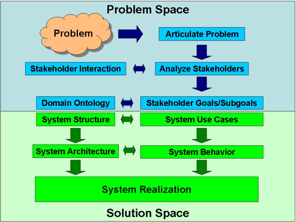
As noted above, identifying the problem to be solved is a key element in OOSEM and every MBSSE implementation. Without a well-defined and detailed problem statement to serve as a starting point, the systems engineering process can be fraught with challenges and setbacks. One key to problem definition in OOSEM is establishing a systematic approach to identifying all the stakeholders. Inclusion of all stakeholders leads to a comprehensive understanding of the needed system performance (Figure 2). System failure can result from missing one or more key stakeholders. To avoid that situation, a structured approach to problem definition and stakeholder identification is needed, using questions such as:
- What is the context of system use; who or what interacts with the system?
- Who experiences the problem(s) to be solved?
- Who has the knowledge to provide a solution?
- What groups are involved throughout the product lifecycle?
- What are the operational scenarios and conditions?
- Who will pay for the system, and are they users of it?
- What are the standards, regulations, and policies that must be taken into consideration?
Fundamentals of INCOSE OOSEM
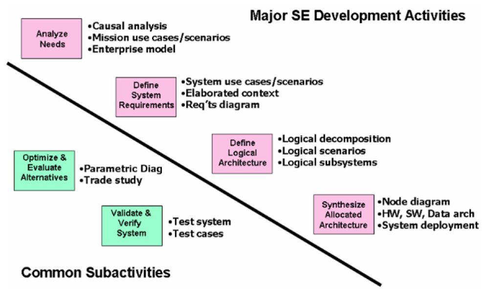
As defined by INCOSE, MBSE, and therefore OOSEM, must support the definition of system requirements, system design, system analysis, and system verification and validation. The fundamental activities include (Figure 3):
- Coordinate and implement system architecture and design and define the relationships between system development activities.
- Implementation based on SysML.
- System performance analysis performed using parametric diagrams combined with weighting factors and value measures to arrive at optimal configurations.
- External modeling and simulation are optional.
- System testing, validation, and verification are separate processes from the primary development activities.
Summary
OOSEM is an MBSE approach from the OMG that combines object-oriented concepts with traditional systems engineering practices. It’s generally implemented using SysML and takes place in a series of stages, including definition of requirements, requirements analysis, system design, system implementation, validation, and system performance verification. A complete definition of the requirements based on a thorough understanding of the problem(s) to be solved is necessary for the successful completion of an OOSEM project. In addition, INCOSE has identified major OOSEM development activities and common sub-activities.
References
Applying Object Oriented Systems Engineering to Complex Systems, IEEE International Systems Conference
Object-Oriented SE Method, INCOSE
Object-Oriented Systems Engineering for Infrastructure Projects, Shoal Group
Using an Object-Oriented Development Approach, Oracle


