
Education for electronics design tends to have a fair amount of math in it but how much is really required nowadays in order to design electronics? You certainly need some, but a high percentage of what you learn at college or university is likely to be unused once you leave, although this does depend on your career choice after university. That does not mean it was wasted time learning math in the first place, but what skills do you need to retain or which do you really need if you are self learning electronics?
 With software such as Mathcad to help solve equations; SPICE to simulate designs; software which can design digital and active filters as well as passive RF filters; it would seem that you almost don’t need to calculate anything provided you can understand and use the software effectively. There will always be a need for someone to be able to work out the most complex problems otherwise there will be no one to write the software necessary to save us having to do the calculations.
You don’t need to know about Laplace transforms or Z-transforms in order to use commercial software to help your design, in the same way that it isn’t essential to know the inner workings of the BSIM4 SPICE MOSFET model in order to use SPICE simulation software. However, it is useful to be able to do some calculations and manipulate some equations yourself. For example, an amplifier using a basic opamp has the gain set by the ratio of two resistors so being able to work out what they should be by hand is preferable to iterating with a simulator. So, an understanding of simple equations and basic algebra for manipulating and rearranging equations is useful. An understanding of basic algebra and the ability to solve simultaneous linear equations is essential to be able to use Kirchoff’s and Ohms law which are some of the basic building blocks of simple electronics. Norton’s theorem and Thevenin’s theorem are two more basic theorems requiring a knowledge of algebraic methods.
Calculus is also pretty useful. While you might think you can get away without it, some simple equations are simply derivations of others with a bit of differentiation or integration thrown in. For example, the charge in a capacitor is Q=CV where Q is the charge, C is the capacitance and V is the voltage. If you differentiate it with respect to time you get
dQ/dt = C dV/dt.
As rate of change of charge is actually current, i = C dV/dt or more usefully, dV/dt = i/C which tells you the rate of change in the voltage of a capacitor from a charging (or discharging) current. While you could always try to look everything up in a book, it is quicker if you can remember a few equations and derive the rest yourself (or remember them all).
Solving simultaneous linear equations is fairly essential in my experience. Take a common problem I have often seen people asking – shifting the range and level of an analog signal to suit an analog to digital converter (ADC). It might also involve inverting the signal as well. The question is something like “… I have a 0 – 5V signal and need to to drive my ADC which needs 1.25V +/-0.5V, so 0.75V to 1.75V range. How do I do it? …”. It is easy to see that the 5V signal range is now 1V so the signal needs reducing but the level shift seems to be tricky to some people and needs some basic math to solve.
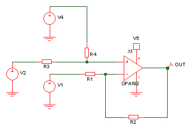
The direction of the signal may also need reversing so 5V input becomes 0.75V and 0V input becomes 1.75V. A generalized differential opamp circuit is one solution to the problem, but how do you choose the component values? Which voltage will be the input and which voltage will be fixed?
If you need signal inversion, V1 will be your input. If you don’t need inversion then V2 or V4 will be the input voltage. V2 and V4 are interchangeable because they both feed the same node and only differ due to the different values for R3 and R4. While you could find the required values by trial and error (or intuition), you could also solve it mathematically. You will need to pick some value for two of the resistors, say R4 & R2 and then choose which of V2 or V4 to use for the signal if you don’t require signal inversion. Then you analyze the two extreme cases – Vin = 0V, Vout = 0.75V and Vin = 5V, Vout = 1.75V. A combination of Kirchoff’s law and Ohms law will be required to analyze the opamp circuit. V2, V4, R3 and R4 will give you the voltage on the non-inverting opamp input. Similarly, Vout, R1, R2 and V1 will give you the voltage on the inverting opamp input. The inverting and non-inverting inputs will have nominally the same voltage. So, you have two simultaneous linear equations but 4 unknowns. With the two extreme values, you will have two more equations so 4 equations and 4 unknowns (remember we fixed R4 & R2). So, it is solvable with some basic math.
If you don’t like the values for R3 or R1 you end up with (too high or low) then the values can be scaled afterwards. One solution would be:
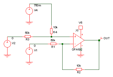
V2 is the input voltage, V4 is the fixed offset voltage and V1 is zero meaning R1 can simply be connected to 0V. In order to avoid having a 0.75V reference voltage you could use two resistors for R4 – one connected to +5V and the other to 0V. This is where a bit of knowledge of Thevenin’s theorem is useful. In this case you would be applying it backwards. Thevenin’s theorem represents any linear network of voltages, currents and resistors with a single voltage source with a single series resistor. We have the single voltage source and resistor and want to replace it with something with two resistors and a voltage source but that behaves the same. You will end up with simultaneous equations to solve again because you need the open circuit voltage to be 0.75V but you need the impedance to be 10k. So, a bit of basic math should bring you to the following solution:
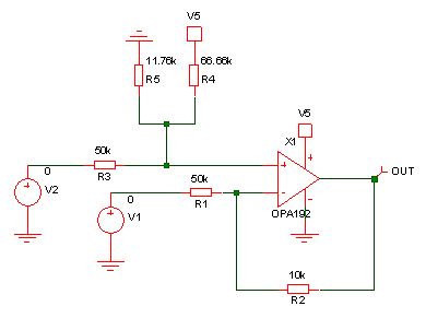
Simulation will help to prove you have the values correct before you build it. While intuition may get you the 0.75V/10k ohm solution, turning that into a combination of two resistors from the 5V supply is easier by a calculation that guesswork.