
The laws of physics work against RF engineers, forcing design tradeoffs in mmWave systems. Beam steering, frequency reuse, and greater spectral efficiency can help.
5G provides data rates greater than 2 Gb/sec, latency below 5 msec, high capacity, and network slicing. These advances bring new opportunities to further improve spectrum efficiency, RF coverage, and access networks. How?
To reach high capacity, 5G will need to use existing C-band spectrum and mmWave frequency bands. The mmWave signals impose challenging propagation conditions that large antenna arrays can alleviate. Antenna array need RF circuits behind each radiating element.
5G systems will deploy a mix of access points and even smart relays to reach users. The architecture of these access points should scale with coverage area. For example, a nanocell may use a 2×2 antenna array, while a macrocell may use a 16×16 array. Under ideal conditions, both the nanocell and macrocell access points would use identical RF components behind each antenna element. Such a design would require a novel RF architecture.
mmWave bands
Most cellular frequency bands operate from 700 MHz to 3.5 GHz. The bandwidth allocated in these frequency bands is typically no wider than 20 MHz, which can support data transmission rates of 100 Mb/sec. The tradeoff comes with greater range from lower frequencies.
To achieve wider bandwidth and higher data rates, network operators use mmWave frequencies at 24 GHz to 30 GHz, 37 GHz to 40 GHz, and 52 GHz. These mmWave frequencies are often called frequency range 2 (FR2). mmWave bands offer two advantages:
- Lower cost: Many mmWave bands cost the operator less to acquire. These bands can cost two orders of magnitude less per hertz when compared to the cost for licenses in the sub-1 GHz bands.
- Although mmWave bands offer terrific bandwidth, they suffer from severely limited propagation distance. Thus, operators use a mix of lower and higher frequency bands to get coverage and capacity. They can, for example, service a campus, sports arena, or similar hot spot with mmWave base stations and offload their lower band frequencies that cover wider areas.
As a radio wave’s wavelength shortens, it becomes more susceptible to blockage by objects, foliage, and even heavy rainfall. A signal’s ability to penetrate an object depends on its wavelength. As a rule of thumb, an object that has the width of a wavelength can block that radio frequency wave. For example, at 700 MHz the wavelength is around 42 cm whereas at 30 GHz the wavelength is 10 mm. A tree leaf’s dimension is closer to 10 mm than 42 cm. Thus, trees block millimeter waves.
Radio waves travel from transmitter to receiver through four modes: they propagate in a straight line (line of sight), get reflected from a building, get diffracted or bend around obstacles, and get scattered from rough surfaces. When a transmitted signal propagates, the received signal varies in amplitude, a condition called fading. Measurements show that millimeter waves, on the other hand, get blocked and experience far less diffraction, reflection, and scattering. Therefore, mmWave RF waves are restricted to line-of-sight (LOS) travel. They don’t fade but undergo severe path loss.
As mmWave signals travel along a line-of-sight path, they lose power with distance, called path loss. For example, at 900 MHz, the path loss is around 91 dB/km but can reach 121 dB/km at 28 GHz. That 30 dB difference or 1000 times more loss than at 900 MHz. Additionally, these millimeter waves further attenuate from foliage, windows, and rain. A tree can attenuate a signal by 6 dB/km, and a tinted glass window can attenuate a transmitted signal by 40 dB. Fortunately, antenna technology mitigates loss at these frequencies.
Antenna arrays adjust amplitude and phase to radiate power in a narrow beam, called beamforming or beam steering. Narrow beams maximize line-of-sight travel and eliminate diffraction, scattering, or reflections from objects. With wide beams, the radiated power has a higher probability of hitting a building and getting blocked, as shown symbolically by the yellow beam in Figure 1.
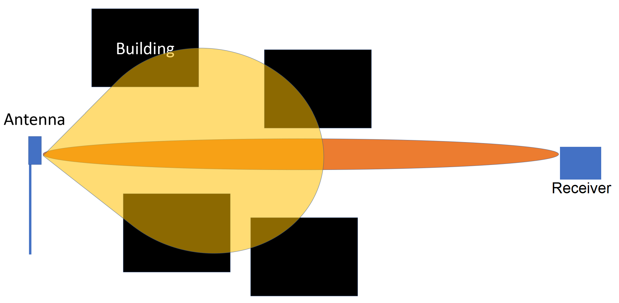
Figure 1. A narrow beam can miss possible blockages, letting its full power reach the receiver.
The concentration of an antenna’s radiated power in a direction is called its directivity, defined by its half-power beamwidth (HPBW). This value is the beamwidth measured where the power is half the peak power (3 dB down from the peak). The HPBW of an MxN element antenna array is inversely proportional to the number of elements and the element spacing. Hence, by controlling the number of antenna elements and their spacing, you can control the beam width and directivity.
Each phased array antenna element needs electronics such as a beamformer, power amplifier (PA), and low noise amplifier (LNA), etc. Hence, as the number of antenna elements increases, the cost of the system increases.
Capacity and Spectral Efficiency
Capacity can be defined as Data Rate/MHz/Unit Area.
Therefore, to secure higher capacity, the reuse factor must be reduced, and the spectral efficiency must increase.
Figure 2 illustrates the concept of frequency reuse. The sectors or cells marked by the red “>” shape and the yellow arrow illustrate how far away the same frequency can be reused.
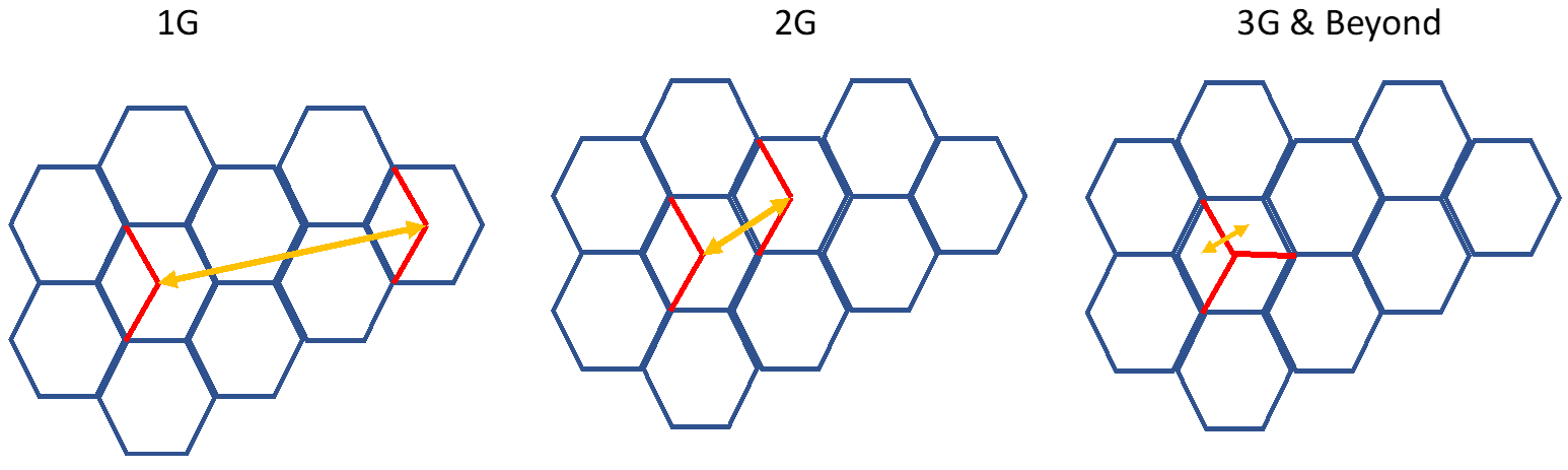
Figure 2. Frequency reuse patterns have changed with each generation with wireless technology.
The capacity of cellular communication is limited by interference on the downlink (communication from base stations to mobile devices). Separating frequencies by distance avoids interference. Mitigating or canceling interference increases capacity by reusing frequencies at closer separation distances. Massive MIMO, using multiple antennas and signal processing, allows tighter reuse of the same channels to increase capacity.
An increase in spectral efficiency — measured as bits/second/Hz — also increases capacity. In GSM (2G) the spectral efficiency is 1.36 bits/sec/Hz, which means GSM allows transmission of 272 kb/sec in a 200 kHz channel. 3G using 16QAM modulation with, say, a rate of ¾ coding gives a spectral efficiency of 3 bits/sec/Hz. 5G uses 64QAM, and a coding rate of approximately 9/10 coding gives around 5.5 bits/sec/Hz. Therefore, with 400 MHz bandwidth, you can achieve 2.2 Gbps.
Spectral efficiency determines the data rate in a channel while frequency reuse determines how often a network can reuse the channel to accommodate users.
Mixed cells or access points?
To optimize coverage and capacity, operators will use mixed cells. For wide coverage, network operators will use gNodeBs (gNBs, base stations) to serve many users over an area. gNBs radiate higher power than small cells. To cover a hotspot with many users such as a campus or sports arena, however, a network could use smaller cells, each with lower power. The large coverage area could use C-band spectrum while the hotspot could use mmWave spectrum. This offers the operator the flexibility of using hotspots to offload the large cells. Hence, by using different size cells operating on different frequency bands, the operator could optimize coverage and capacity.
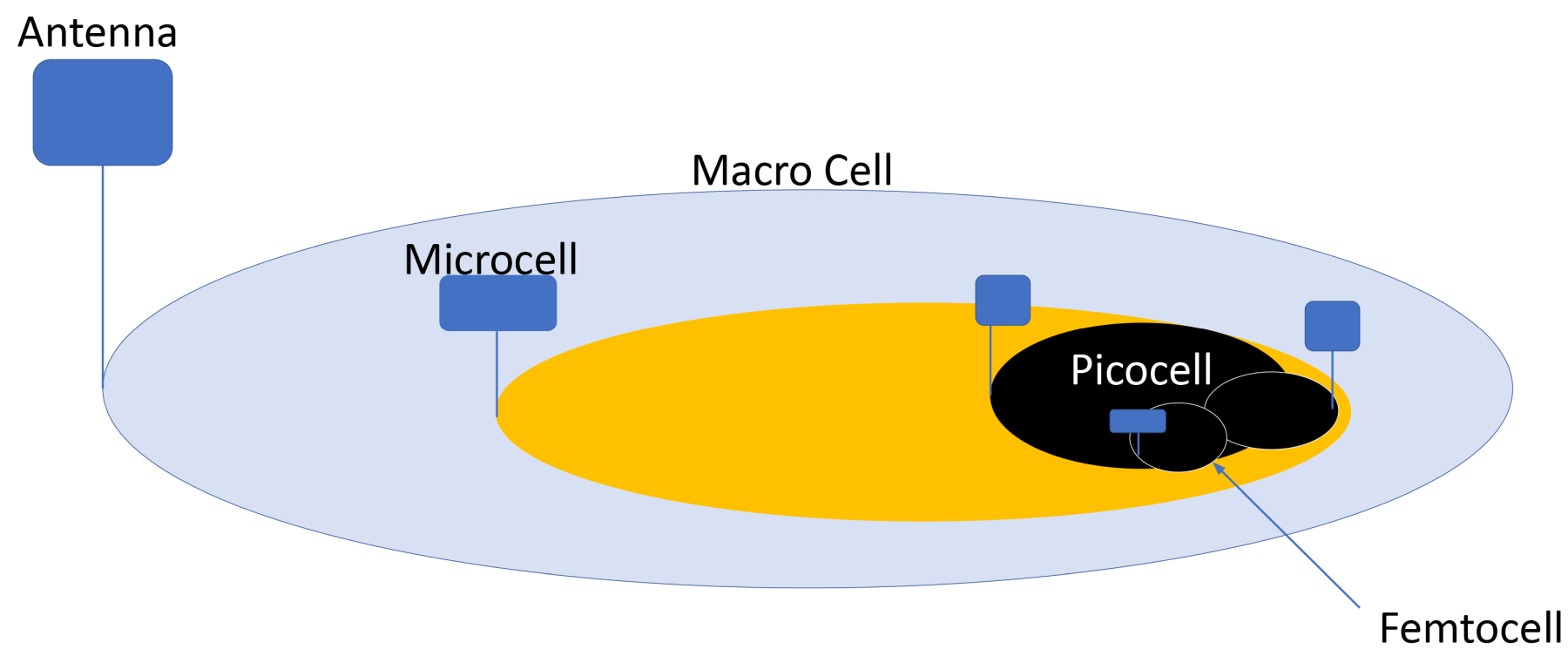
Figure 3. Cell splitting and nested cells results in higher capacity than with a macro cell alone.
Figure 3 illustrates the point. A cell’s antenna pattern covers an area. Each cell can be successively split, using lower height antennas and lower power so that cells don’t overlap in frequency. If they do overlap, they are differentiated in power and interference cancellation. By splitting a cell, the operator can reuse the same frequency, resulting in frequency reuse gains. Splitting the frequencies between bands reduces interference.
Assume the system supports 100 users in a 5 MHz channel in the macrocell. This macrocell is split successively into smaller cells using less power with each split. If the microcell supports 40 users, the picocell supports 10 users, and the femtocell supports five users, the network now supports 135 users versus the original 100. These users do interfere with each other but using antenna arrays (massive MIMO) and advanced signal processing, the user signals can be separated.
For 5G to achieve the best coverage, operators use an increasing mix of gNBs, small cells, and smart repeaters. Each of these access points use antenna arrays, resulting in an increased opportunity for RF chips and products. Furthermore, 5G mmWave technology offers an opportunity to provide cost-effective broadband to residences without the need to lay fiber. An exterior 5G repeater or small cell can beam data at 2 Gbps to customer premises equipment (CPE) that can receive and redistribute the signal throughout the house. Such systems provide data rates that rival current fiber offerings but also provide very low latency.
RF Architecture
RF front ends for 5G mmWave should address:
- Large antenna arrays to overcome the propagation losses and handle interference mitigation.
- Support for scalable mixed-size cells along with wide operating frequencies and interference cancellation.
Figure 4 shows an example of an RF architecture that supports any size antenna array as a tiled tree of three IC building blocks. The first is a beamformer that contains phase shifters, switches, a power amplifier (PA), and a low-noise amplifier (LNA) to drive, say, a 4 x 4 or 8 x 8 dual-polarized antenna array. A number of these devices combine to drive multiple antenna elements as needed. This device is connected to a second IC comprising mixers for up-and-down conversion. A single mixer chip can drive four beamformer chips. The final IC is the multiband synthesizer, which provides a precise reference frequency reference for the mixers.

Figure 4. A scalable RF architecture can support a variety of antenna array sizes.
The critical RF parameters that determine performance are the output power levels of the PAs, noise figure of the LNA, phase noise (jitter), and distortion measured by error vector magnitude (EVM). Optimizing these parameters across the three chips creates a high-performance system resulting in reductions in power and cost. For example, the synthesizer must have low phase noise to minimize jitter. As the frequency increases, however, the power required to keep the phase noise low also increases. If the synthesizer uses a lower frequency to generate the reference and the mixers had on-chip frequency multipliers, you can save power and generate an accurate reference signal with low jitter.
mmWave bands will find increasing use to meet the requirements of higher capacity through their wider bandwidth. mmWave spectrum in many countries is also much more affordable than lower band spectrum. These bands are, however, challenged by their propagation conditions. To solve this large issue, antenna arrays can be used to enhance coverage as well as mitigate interference. This technique helps increase capacity by using mixed cells (gNBs, small cells, and even smart repeaters) for both capacity and coverage.
 Reza Rofougaran is CTO and co-founder of Movandi and is a leading pioneer, engineering executive, and entrepreneur in wireless system design. He co-founded Innovent Systems in 1998 and is one of the top ten patent holders in U.S. and top twenty patent holders in the world. While at Broadcom, Reza was influential in starting and building the wireless business unit that shipped over 1.5 billion radios per year. Reza holds over 800 issued patents.