
by Michael Harper, Coil Experts, LLC
It pays RF designers to know a few things about the way coil-winding houses fabricate coils.
Inductive coils are ubiquitous in any kind of RF or wireless circuit. But some of the tiny coils that characterize RF work can be challenging to produce. Custom coil designs often get sent to commercial coil winding houses, such as Coil Experts. These winding houses can create devices with highly repeatable qualities. However, not all coil winders are the same. Here are a few things designers might want to know about working with coil winders before beginning the coil design process.
First the basics: Designers must specify more than just the inductance of the coil they need. A commercial coil winder will want to know the general dimensions of the coil including the length-to-width ratio, the coil size and shape, the type and size of the wire, the dc resistance, how the leads should be configured, the type of wire insulation, and so forth.
Fortunately, the equations for calculating many of these factors are well-known and available in handbooks. The coil-design process itself tends to be iterative, with the designer starting with desired qualities and ascertaining through repeated calculations whether the design envisioned is something that works in the real world.
The parameters specified for coils generally depend on the application area. The usual range of inductance for RF coils is in the microhenry range. Coils made for ac and RF circuits have inductance requirements, but perhaps no specification for their dc resistance. In contrast, coils destined for use in dc circuits generally have dc-resistance requirements.
One of the main parameters the designer specifies is the number of turns in the coil. Of course, the number of turns determines the coil inductance to a high degree. A point to note is that the coil winder won’t give a tolerance specification for coil inductance; a batch of coils that all use the same length of wire and the same winding pitch will all provide the same inductance to a close degree. Thus, winding pitch and manufacturing process control basically sets inductance tolerance.
Most coils are wound on round forms, and round coils are the easiest to make. That is because the constant pull on the wire during coil forming puts less stress on the wire than is the case when making coils that are square, rectangular or triangular. The wire experiences a small shock as it is pulled around each corner when making these latter shapes. But this limitation may make it hard to realize such shapes with ultra-fine wire, and the tight process parameters needed for fabrication may be beyond the means of some coil winders. Nevertheless, non-round coils may sometimes be necessary to obtain special electromagnetic qualities.
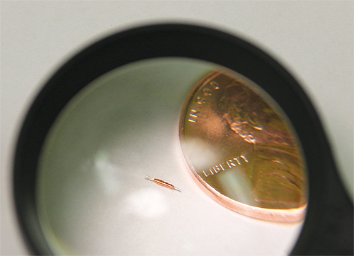
There are also practical limits to the size of the coil. A general rule of thumb is that some coil-winding houses can fabricate coils down to 1-mm diameters. That said, it’s best not to assume smaller devices are impractical. RF designers constantly push the state-of-the-art, so the only real way to ascertain whether a form factor is unfeasible is to discuss it with the coil house.
The same can be said for wire diameter. The RF designer always specifies the wire size. Electrical current is the primary factor that determines minimum wire diameter. Typically, RF coils are low current devices. Their wire size usually ranges from ultra-fine (58 to 50 AWG) to very fine (49 to 40 AWG) to fine (39 to 30 AWG). Clearly, coil fabricators can work with surprisingly small wire diameters, considering that 58 AWG (0.00991 mm) wire is so delicate that it can break if someone breathes on it too hard.
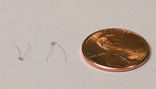
In cases where an ultra-fine wire would be adequate to handle the current involved, designers often use a larger wire simply for mechanical strength and easier handling. For example, the strength of the leads is often a major concern. Ultra-fine wire leads are quite fragile, so designers might specify thicker wire.
Wire size and coil dimensions also impact costs. The finer the wire, the more fragile the coil. And fragile coils often can only be handled with tweezers under magnification. They are usually packed in some sort of egg carton tray. The more fragile the coil, the more delicate the handling and packing procedures. Delicate handling and packing costs more.
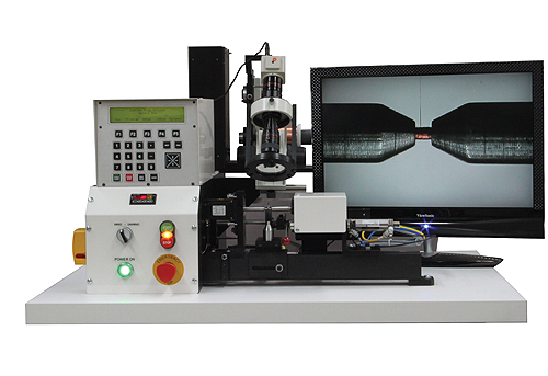
Small coils also may only be practical in relatively high volumes. That’s because microcoils are difficult to make without the use of specialized machines. Only coil winders that deal in relatively high volumes are likely to have the necessary coil winding machines. Similarly, not all coil winders have the facilities to handle micro coils. Older generic coil winding machines often can’t provide the necessary accuracy.
Finally, RF designers also specify the insulation used on the coil. Selection criteria for coil insulation typically includes the level of heat expected and whether there will be mechanical or chemical stress. Biocompatibility also becomes an issue in all medical applications.
References
Coil Experts, LLC
coil-experts.com