An analog switch is an IC that can be used to control connections to analog and digital signals. These switches provide bidirectional connections when “on” and high impedance paths when “off.” There’s a wide range of analog switches for special functions. In some instances, they are used in place of mechanical switches. In other embodiments, they can perform functions not possible with mechanical switches.
This FAQ begins with a review of analog switch IC basics, considers some key specifications, presents some specialized analog switch types like high-frequency T switches, high voltage switches, and load sensing switches, and closes by looking at how analog switches can be used in amplifier gain adjustment in data acquisition (DAC) systems and how they contribute to medical ultrasound imaging applications.
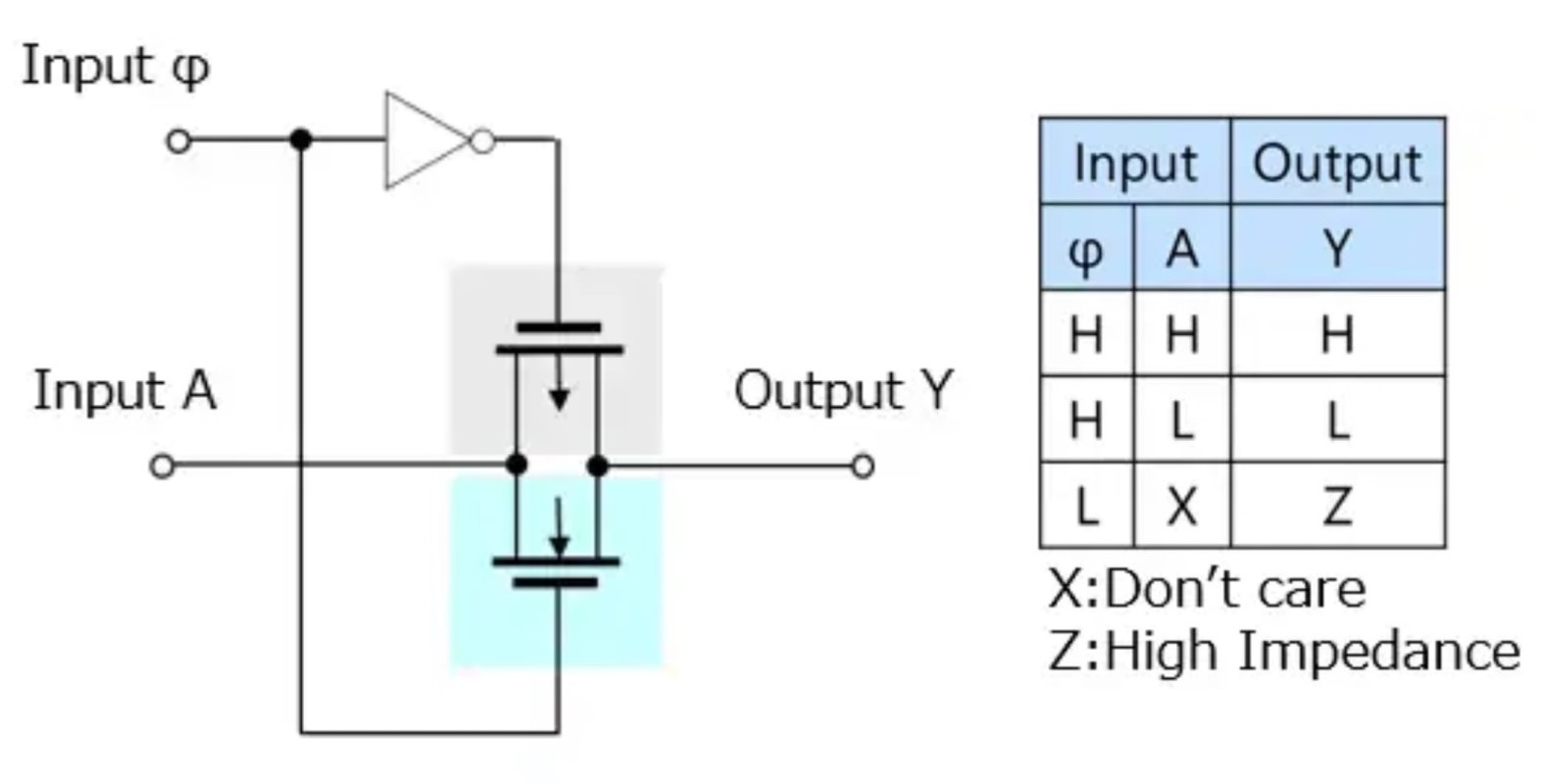
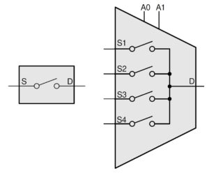
Basic analog switches are three-terminal devices with input, output, and control pins. When the control input is high, the output pin reflects the state of the input pin, which can include various levels of impedance, variable signals like sine waves, and digital signals. When the control pin is low, the output sees a high impedance (Figure 1).
Analog switches are available in the same configurations as mechanical switches like single pole single throw (SPST), single pole double throw (SPDT), double pole double throw (DPDT), and more. Unlike mechanical switches, analog switches provide bounce-free switching. Like mechanical switches, they are available in normally closed (NC) and normally open (NO) configurations. Large numbers of analog switches can be co-packaged for applications like medical ultrasound imaging. They can also be assembled into multiplexers and demultiplexers (Figure 2).
Basic characteristics and specifications
Single power supply refers to devices with only a positive power supply pin with reference to ground.
Dual power supply refers to devices with positive and negative supply pins with reference to ground.
Switching speed is how quickly the switch changes its condition from on to off and off to on, many switches can reach speeds of a MHz or faster.
Bidirectional signal path, analog switches are bidirectional and conduct (almost) equally well from source (S) to drain (D) or from drain (D) to source (S), however, there are more detailed specifications to consider like on-resistance flatness, on-resistance mismatch and cross talk as listed below.
Switch withstand voltage is often 15 Vdc or less; common voltages include 3.3, 5, 12, and 15 Vdc. Analog switches are also available that can handle 25 V and higher.
Maximum switch current is typically a few hundred mA, there are relatively fewer examples of analog switches rated for an amp or more. High-current applications often use solid-state relays instead of analog switches.
On resistance can range from several ohms to several hundred ohms and may not be exactly equal for both signal paths.
Turn-off impedance is not always explicitly included in data sheets but can be calculated using the OFF leakage current specification.
In addition to these basic characteristics and specifications, there can be further factors to consider, depending on the device and application, DC characteristics, dynamic characteristics, and timing characteristics:
- DC characteristics
- On-resistance flatness
- On-resistance mismatch between channels
- Supply current
- OFF leakage current
- Powered-off I/O pin leakage current
- ON leakage current
- Control input leakage
- Dynamic Characteristics
- Bandwidth
- Channel-to-channel crosstalk
- Insertion loss
- Off-capacitance source and drain
- On capacitance source and drain
- Charge injection
- Off-isolation
- Total harmonic distortion and noise, THD + N
- Timing Characteristics
- Device turn on time from enabling pin
- Break-before-make time
- Make-before-break time
- Propagation delay through the switch
- Output-to-output skew
- Fault response time
- Fault recovery time
As is the case for every electronic device and system, anomalies and faults can occur, and protection functions are needed to ensure robust system operation. Some common protection functions for analog switches include:
- Overvoltage and undervoltage protection – when the input voltage exceeds defined thresholds (either too high or too low) voltage, the switch enters the high impedance state, isolating the signal path, and protecting downstream components.
- Fail-safe logic – ensures the switch stays off and the voltage on the logic pin (VSEL) does not back power VDD when VSEL is greater than VDD.
- Injection current control – when the switch is disabled (in a high impedance state), any current injected into the signal paths is shunted to ground, preventing errors on the active signal path.
- Integrated pulldown resistors – internal resistors on the logic pins to ground to ensure the pins are not floating.
- Latch-up immunity – ensures that the switch is immune from latch-up caused by electrical overstresses, electrically fast transients, injected currents, and other conditions.
Specialized analog switches
Many types of specialized analog switches are available.
High-frequency T-switches are designed for use in video and other applications that operate at 10 MHz or higher frequencies. These switches are often designed with higher turn-off isolation compared with general-purpose analog switches. In some instances, the isolation can be -80 dB or higher. In some designs, the crosstalk increases at higher frequencies.
High isolation switches are available with galvanic isolation capable of blocking ±600. They are also available with multiple switch arrays with 110dB switch-to-switch isolation at 5 kHz. They include independent switch current limiting and switch-pair thermal shutdown protection functions. High-isolation analog switches are designed for use in a range of applications:
- AC mains monitoring
- Automatic test equipment (ATE)
- Battery monitoring and charging
- Industrial controls and monitoring
- Instrumentation
- Test and measurement
Load-sensing switches are available for Kelvin testing in ATE equipment. They are designed for high-precision and long-distance measurement applications. These devices are dual switches in an SPDT configuration that include a high-resistance switch for detecting a voltage or switching protection lines and a low-on-resistance, high-current switch for load currents. Load switches can be deployed using 2-wire or 4-wire (Kelvin) topologies.
Calibrated multiplexers (cal-muxes) are low-voltage multiplexers with internal precision resistor dividers that generate precise voltage ratios using the internal supply voltage or an external reference voltage. The internal resistors are configured through a digital interface. Cal-muxes combine the functionality of an external resistor string, multiplexer, and logic gates in a single device. They can be especially useful for calibrating and monitoring high-precision ADCs in data acquisition systems (DACs).
Data acquisition
Analog switches and multiplexers can be used in a variety of ways to enhance the functionality of DACs. The analog switch and multiplexer used in DACs need low charge injection and parasitic capacitance to minimize switching errors and settling time in multiplexer, sample, and hold circuits. Two examples of DAC applications include varying the gain of an op-amp as needed by specific operating conditions and connecting multiple sensors to a single line (Figure 3). These solutions can support high-density precision DAC systems for industrial, medical, and other applications.

Ultrasonic imaging
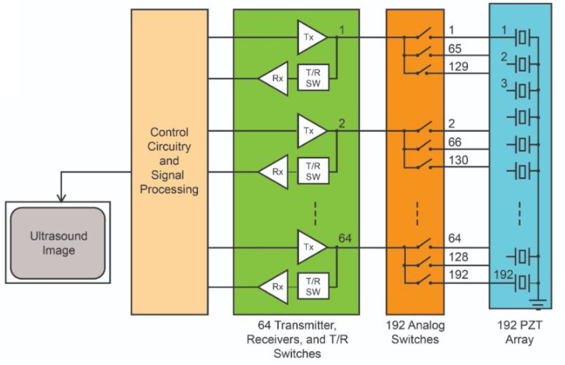
Medical ultrasound imaging uses large numbers of piezoelectric transducers (PZTs) to create acoustic waves. These systems require the precise control of at least 128 PZTs. Figure 4 shows an example of an ultrasonic imaging system using a monolithic array of 192 high-voltage analog switches with 192 PZTs connected to 64 transmitters/receivers (T/Rs). The system operates in a series of cycles. In the first cycle, the outputs of the 64 T/Rs are routed with the analog switches to drive PZTs 1 to 64. In the second cycle, after the return signals have been received, the analog switches route the outputs of the 64 T/Rs to PZTs 2 to 65. The third cycle consists of the analog switches routing the outputs of the T/Rs to PZTs 3 to 66. The cycles continue until all the PZTs have been energized and the return signals received. After about 50 ms, 192 cycles have been completed and one frame of the image can be created.
Summary
Analog switches are important components that can enable high-density and high-performance solutions in a wide range of applications in automotive, consumer, industrial, instrumentation, medical and military systems. They are available in the same configurations as mechanical switches but operate without contact bounce. While their operation is simple in theory, specifying analog switches requires careful attention to many specifications. Specialized analog switches and multiplexers are available that have been optimized for specific applications.
References
Analog Switch: Types and Application, Utmel
Combinational Logic: Analog Switches, Toshiba
High-Voltage Analog Switches for Medical Ultrasound, Monolithic Power Systems
Multiplexers and Signal Switches Glossary, Texas Instruments
Selecting the Right CMOS Analog Switch, Maxim Integrated

