Voltage references are small components that can have a significant impact, either positive or negative, on system performance. They are precision devices that maintain a constant voltage output even in the presence of changes in temperature, input voltage, and other external parameters. When measuring the analog world, voltage references ensure that data converters, detection circuits, and other interface circuits have a rock-solid reference for quantifying length, pressure, speed, temperature, and other analog parameters.
This FAQ briefly reviews types of voltage references like shunt vs. series designs and Zener vs. buried Zener vs. bandgap, along with their performance capabilities. It looks at multiple dimensions of voltage reference accuracy, including bits vs. ppm vs. percentage, along with other specifications, including temperature coefficient, temperature hysteresis, line and load regulation, drift, dropout voltage, load capacitance, and closes with a look at how to improve temperature stability and controlling noise in voltage reference circuits.
Shunt references
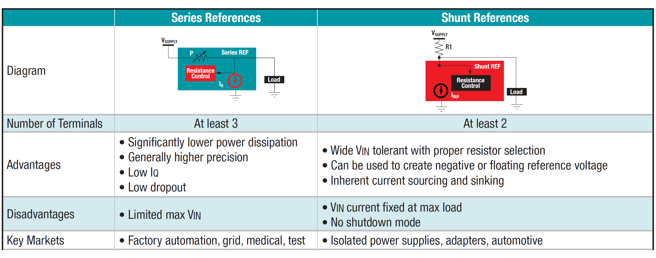
A shunt voltage reference is implemented with a three-terminal circuit with one terminal of the reference connected to ground and the other reference terminal connected to a resistor with the opposite end of the resistor connected to the supply voltage. The point of connection between the resistor and the shunt is the output. The advantages of shunt references are simplicity, compactness, and good stability over wide current and load ranges (if properly implemented). They can also be used to provide negative voltage references, and they can be used with very high or very low supply voltages. The output can be a few millivolts (mV) below the supply voltage. However, if the supply voltage or load current are expected to have large swings, things can get a little challenging. The resistor must be sized to accommodate variations, resulting in increased power dissipation, which can heat the reference and interfere with accuracy.
Series references
A basic series voltage reference is implemented with three terminals, like a shunt reference. A series reference is essentially a voltage-controlled resistance in series with the load. It operates by varying its internal resistance so that the input voltage minus the drop across the variable internal resistance produces a constant reference voltage at the output, like a low drop out regulator (LDO), but with high precision. Also, like an LDO, a series voltage reference has a small quiescent current when the load is zero. They consume a nearly constant amount of supply current over a wide range of input voltages and conduct significant levels of current only when required by the load. Series references are useful in applications with high load currents and when there are large changes in load current or supply voltage. Shunt and series voltage references provide different sets of performance tradeoffs and are useful in different ranges of applications (Table 1).
In addition to choosing between series and shunt configurations, voltage references can be implemented using different semiconductor technologies.
Zener-based references have a predictable reverse voltage that’s very constant over time and can provide good temperature stability, especially if operated over a narrow temperature range. Careful fabrication of the Zener element can minimize variations in initial voltage. And circuits can be added to compensate for initial voltage variations and temperature effects. Circuitry can also be added to support a range of output voltages. A limitation of Zener references is noise related to impurities on the surface of the die. Those noise issues can be minimized with a buried Zener where the Zener element is literally buried below the surface of the die. Limitations of Zener references include the need for supply voltages above 7 V and their ability to support a relatively narrow range of output voltages.
Bandgap references can overcome several of the limitations of Zener-based designs. Bandgap references can support a wider variety of output voltages and generally require less than 100 mV of headroom in the supply voltage. They are more complex and require two transistors and resistors to implement. The bandgap operation is based on bipolar junction transistors. The two transistor junctions have different current densities and, therefore, different temperature coefficients. The voltages with opposite temperature coefficients are subtracted from each other, resulting in a nearly flat temperature curve. It’s almost flat since the temperature coefficient of the base-emitter voltage is about -2 mV/°C. A compensation circuit can be added to flatten the curve further. These references typically produce an output voltage of around 1.25 V, close to the theoretical 1.22 eV band gap of silicon at 0 K. Hence the name bandgap.
Fractional bandgap references also use a combination of transistors and resistors to produce a reference voltage but are current-based devices compared with conventional bandgap references that are voltage based. In a fractional bandgap reference, a resistor element generates the reference voltage. Varying the value of the resistor can produce reference voltages much lower than the typical 1.25 V bandgap reference. Like the case of bandgap references, circuitry is often added to fractional bandgap references to improve temperature performance.
Voltage reference specs
Voltage references can be deceptively simple in appearance. However, accurately and thoroughly specifying these devices is complex. The following are some of the considerations:
- Initial accuracy is typically specified as a percentage (usually between 0.01% and 1%) or in parts per million, ppm (typically from 100 to 10,000 ppm).
- Temperature coefficient is usually measured in ppm/°C and can be specified over several temperature ranges like 0 to 70°C, -40 to 85°C, etc.
- Temperature hysteresis measures the change in Vref due to one or more thermal cycles and is typically measured in ppm.
- Line regulation is the variation of Vref with changes in supply voltage measured as a percentage or in ppm. This applies only to series references.
- Load regulation is the variation of Vref with changes in load current measured as a percentage or in ppm.
- Long-term stability or drift quantifies the typical or maximum change in Vref after 1,000 hours of continuous operation under nominal conditions.
- Dropout voltage is the minimum allowable difference between input and output voltage that can support a reliable Vref and applies to series references.
- Supply current includes the specification of quiescent current for series references and minimum operating current for shunt references.
- Ground current is measured at a defined load and applies to series references.
- Load capacitance measures the ability of the reference to drive a capacitive load.
- Noise is usually measured in mV peak-to-peak at a given output.
- Transient response is specified separately for step changes in line and load conditions and measures the time needed for a return to the nominal Vref.
- Settling time measures how fast Vref stabilizes after power is turned on.
Improving temperature stability
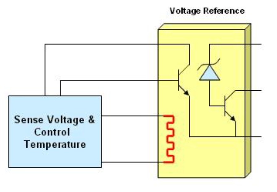
High stability over a wide temperature range is an important consideration in many industrial, communications, test and measurement, and medical systems. Voltage compensation techniques with a temperature feedback loop can provide some measure of improvement in temperature stability. Another and better technique is to use so-called oven-stabilized devices. Instead of providing temperature feedback compensation, oven stabilization provides a constant operating temperature for the voltage reference, nearly eliminating all stability problems related to temperature changes.
One approach to oven stabilization is to include a heating element on the voltage reference and use an external temperature control element to monitor the temperature and maintain it constantly (Figure 1). Oven stabilized voltage references have stabilities of 0.1 to 0.5 ppm/°C over the entire operating temperature range. Devices without oven stabilization are usually rated from 2 to 10 ppm/°C.
Reducing Vref noise
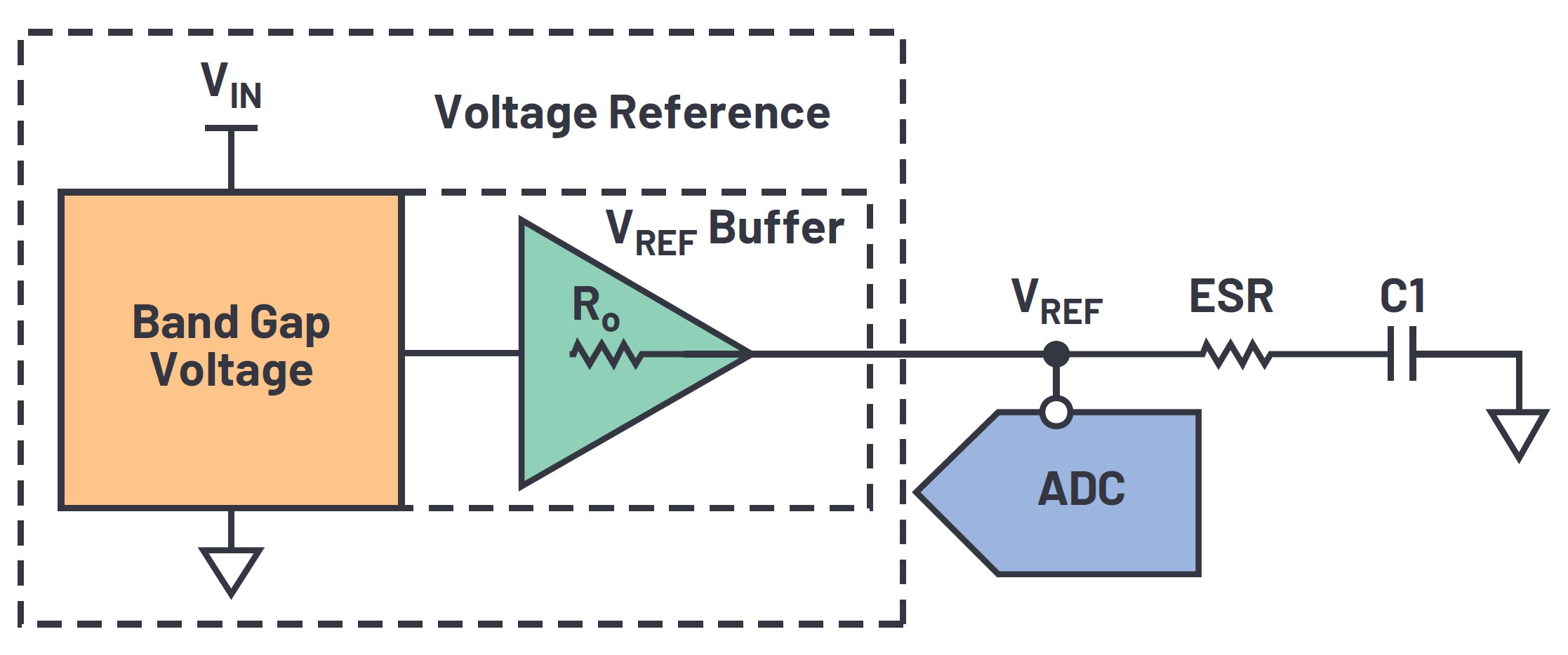
Voltage reference noise can limit performance in ultrahigh precision measurement applications in defense, oil and gas exploration, and pharmaceutical and medical devices. For example, high-precision lab balances are used in pharmaceutical development and can require 0.0001-milligram resolution for measurements of about 2 grams. That requires an analog-to-digital converter (ADC) with over 24-bit resolution.
One way to achieve that level of precision is to drive the ADC with a voltage reference through a low pass filter (Figure 2). The filter consists of C1, an external reservoir capacitor, the equivalent series resistance (ESR) of C1, and the op amp’s output impedance in the voltage reference. C1 also helps to compensate for voltage spikes resulting from changing power demands by the ADC. Tradeoffs for the improved precision include an additional component, a slightly larger solution that consumes a little more power, and a few ppm lower dc accuracy.
Summary
Voltage references are important components in many applications, especially when the analog world needs to be digitized. There are a variety of voltage reference architectures and several semiconductor technologies that can be used to implement voltage references. Even though they are simple devices, they have many important performance specifications to consider when designing them into an application. For the most critical performance parameters, like temperature stability and noise, additional components can be added to improve their performance.
References
How to Choose a Voltage Reference, Analog Devices
Precision Voltage Reference Testing, NI
Tips and Tricks for Designing with Voltage References, Texas Instruments
Why Does Voltage Reference Noise Matter?, Analog Devices