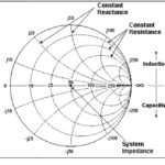
In circuit designs spanning low-frequency audio through high-frequency RF, there’s considerable discussion about impedance matching between components or subcircuits, with various tools such as the Smith chart with is used to facilitate the matching.
Q: What is impedance matching?
A: Impedance matching means that a signal source sees a load impedance which is the complex conjugate of its own impedance.
Q: Remind me: what is “complex conjugate”?
A: Every source or load has an impedance that can be expressed by a complex number, with a real (R) and imaginary (X) part: R + jX. In a complex conjugate, the imaginary part has the opposite sign: R – jX (Figure 1).
Q: Why do we need to conjugate-match impedances?
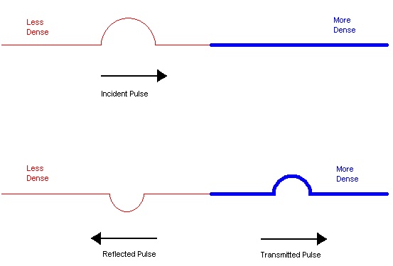
A: There are two related reasons: first, it can be proven analytically that doing so maximizes the transfer of power between the source and load, which is always a good thing; second, it eliminates — or at least minimizes — reflections of signal energy from the load back to source due to impedance mismatch and “bumps” at impedance-transition points as shown in Figure 1. These reflections not only distort signals, but their returning energy can actually damage the source circuitry.
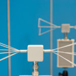
Q: What are some source/load pairings or transition locations?
A: Almost any connection between function blocks or circuit elements can be considered a source/load pairing. Among these are a generator and a lamp as load (incandescent, CFL, or LED), an antenna feeding a receiver front end, a power amplifier driving an antenna via a transmission line, or even an audio amplifier powering loudspeakers.
Q: What are some common impedance-match combinations?
A: Among the most common pairings are the 50 Ω/75 Ω transmission line of coaxial cable; a high-impedance vacuum-tube audio-amplifier output of several hundred Ω (yes, they still sues those) to a low-impedance loudspeaker at 8 Ω. These are simple, resistive matches with a reactance (imaginary) value of zero.
Q: Are there non-standard match combinations?
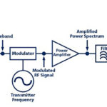
Yes, many are non-standard. For example, the power amplifier output stage of an RF transmitter designed for a 50-Ω purely resistive load may actually be connecting to an antenna with an impedance that is not 50 Ω, and which has a large reactive component due to its physical size, configuration, and placement.
Q: What is done to match the impedances?
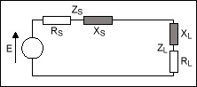
A: The solution is to devise and insert a matching network, comprised of resistive and reactive elements, between the source and load (Figure 2). The network is designed so that the source sees a load impedance equal to its complex conjugate, while the load looking back, also sees its complex conjugate.
Q: What types of matching situations are relatively easy to deal with?
A: Cases, where both the source and load are purely or nearly purely resistive, are easiest to handle since no reactive elements (inductive or capacitive) are needed. For common resistive source/load pairings, such as between a 50- Ω drive as the source and an 8-Ω speaker as load, off-the-shelf devices are available to insert between source and load (these are often called L-pads, T-pads, and pi-pads, depending on their internal arrangement). In some resistive situations, a transformer is used with the appropriate turn ratio needed to provide the resistive-impedance match.
Q: What complicates the matching combination?
A: For many real-world designs the frequency range over which the impedances must match is relatively wide, and so the source and load impedances are shifted. For example, an antenna load may be highly capacitive at one end of the band, and inductive at the other. In this case, the matching circuitry also may have to be adjustable depending on where in the spectrum the system is operating.
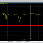
Q: How is mismatch quantified and what is an acceptable level of mismatch?
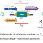
A: Voltage standing wave ratio (VSWR) or simply standing wave ratio (SWR) is the most commonly used parameter. Mathematically, it is a function of the reflection coefficient, which describes the power reflected from the antenna. If the reflection coefficient is represented by Τ (Greek letter tau), then the VSWR is defined as (1 + |Τ|)/(1 – |Τ|). The reflection coefficient Τ is also known as s11 or return loss when using “s” (scattering) parameters.
Although the acceptable value of VSWR depends on the specifics of the application and the tolerance of its components for reflected energy, a good rule of thumb is that it VSWR should be 2 or lower. When the match is perfect, VSWR will be equal to 1.
Q; How is the needed matching circuit determined in more complicated situations?
A: Various analytical and graphical tools are available to determine the combinations of resistors, capacitors, and inductors which are possible options. These approaches will be disused in Part 2.
References
- Maxim Integrated, Tutorial 742, “Impedance Matching and the Smith Chart: The Fundamentals”
- National Instruments, “Impedance and Impedance Matching”
- Antenna-Theory.com, “Voltage Standing Wave Ratio”
- University of Kansas, EECs Dept., “Chapter 5 – Impedance Matching and Tuning”
- San Jose State University, “Impedance Matching and Matching Networks”