It is tempting to center your attention only on voltage noise when using operational amplifiers in the circuit. This impulse is attractive because the current noise is always well below the voltage noise specifications. But be careful. Don’t jump to conclusions without looking at all the elements in this noise challenge. This blog explores the amplifier current noise issues and how it can compete with the well-known voltage noise contribution.
What type of op amp are you using?
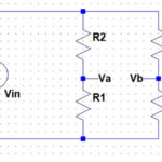
To be confident of your noise calculations, take note of your circuit configuration and op amp type. Op amp circuits most often have resistors at the amplifier input and feedback loop. The resistor elements create flat white noise; however, there is another dynamic to consider. Your amplifier can generate sizable current noise that resistors will further gain to the noise signal. Consider the circuit in Figure 1.

This simple circuit has a large input impedance into the non-inverting input. If the amplifier has considerable 1/f current noise, a significant noise error appears at the input terminal. If you have a high precision low noise system, the proper amplifier selection for this circuit is critical.
Common amplifier choices are between the bipolar and CMOS (Figure 2).
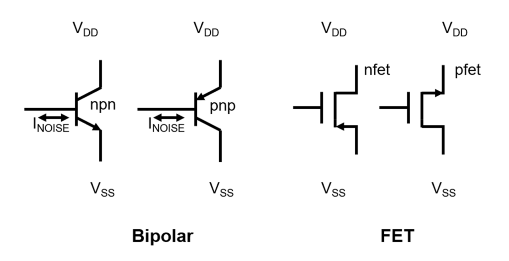
The bipolar amplifier input devices tie directly to n-material or p-material. In both cases, these input devices have higher input bias current and input current noise. The CMOS (Complementary Metal Oxide Semiconductor) amplifier input devices tie directly to the transistor’s gate. The amplifier devices have extremely low input current noise in both CMOS cases, as illustrated in Table 1.
Which amplifier gives the lowest output noise?
The low noise, bipolar amplifier, TI’s OPA227, low voltage noise is instinctively the best choice. But take a second look. The device’s current noise is higher than TI’s OPA132. Carefully compare the low-frequency noise of the two amplifiers. Since this application circuit has high input impedance, the current noise looks incredibly significant. The FET input OPA132 has the highest voltage noise, but the OPA132 low current noise wins the contest for this application circuit.
Surprisingly, the OPA227 has the worst noise, but this is due to the high amplifier current noise that the large input impedance converts to voltage noise. But take a second look. Low impedance applications would likely make the OPA227 the best choice.
The VNO formula applied to the number in Table 1 is:
Where k = 1.38e-23 (Boltzmann’s Constant)
T = temperature and Kelvin
The resistor noise formula is:

To answer the question above is surprising. The amplifier that produces the lowest output noise combines a low-value input resistance and bipolar amplifier.
Conclusion Current noise is a surprise when calculating 1/f noise because we habitually concentrate on the voltage noise and leave it at that. This blog tackles the current noise issue and compares it by working with Bipolar and FET amplifiers.
Finally, the 1/f noise mystery is solved. We saw how to calculate voltage noise in this region and then pull current noise into the discussion. But wait. There is one more issue to consider. In part 3 of this series, we will change the complete amplifier paradigm from looking at the standard bipolar, FET, and CMOS to the zero-drift amplifiers.
References
Noise Reduction Techniques in Electronic Systems, Henry W. Ott, John Wiley & Sons, ISBN 0-471-85068-3
“Understanding and Eliminating 1/f Noise”, Robert Kiely, Analog Dialogue 51-05, May 2017
“8.8 TI Precision Labs – Op Amps: Noise – 1/F flicker noise”, TI Precision Labs Video


