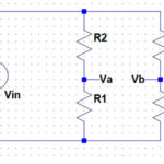
Bipolar operational amplifiers have an essential input bias current requirement. This bias current has to come from somewhere and can be a nuisance in some types of high impedance circuits such as charge amplifiers and transimpedance amplifiers and can result in offset voltages where input resistances aren’t matched. The example shown below has an input bias current of 2.8nA. This is a result of the long-tailed pair tail current of 937nA which is split between the two transistors of the long tailed pair (Q1/Q2) and then divided by the transistor current gain.

While a darlington input stage is one possible solution, that tends to result in a lower bandwidth, as does simply reducing the long-tailed pair bias current. It can also make the circuit more susceptible to temperature related leakage and matching issues.

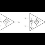
One possible solution is to use input bias current compensation circuitry. This involves generating a current which is equal to the input bias current and feeding that into the opamp inputs so all of the input bias current doesn’t need to come from the external circuitry. An example is shown below:

Here an extra five transistors have been added. Q13 generates a current equal to half the long tailed pair current (it has one emitter whereas Q3 has two emitters). This is fed into the emitter of Q14 to generate a base current which is Q13 collector current divided by the NPN current gain. This is then mirrored with Q6/Q7 and Q8 and fed to the bases of the two input transistors Q1 & Q2. Note that all PNP transistors are dual collector and in the case of Q5 the transistor forms a current mirror without the need for a second PNP transistor.
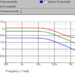
So, if you follow the currents through you will see that we have generated a current to feed into the input transistor bases which is identical to the required input currents. We have an input base current of 2.77nA and a current from the compensation circuit of 2.77nA (2x 1.3886nA as shown in the two collectors of Q6). So, the resulting current which needs to be supplied by the external circuitry is almost zero. In fact in simulations only a residual 1.3pA of the original 2.77nA remains. In reality, the circuit will not normally be that good – the bias current compensation will vary with the voltage on the input pins and will also be dependent on transistor matching.
You can add more transistors to improve the current compensation and to try to make it track with input voltage variation. This can be achieved by making the input current compensation circuit collector-base voltage track the collector-base voltage of the input transistors. This helps to prevent the current error due to the Early effect from affecting performance. However, the circuit shown gives a practical improvement in the input bias current of a factor of more than 10 with no loss of bandwidth. A more sophisticated circuit could improve on that. The circuit could actually be made even simpler by using a dual emitter transistor for Q13 and then using a single PNP for Q6/Q7, relying on the dual collector to split the current to the two input transistors.