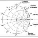
Impedance matching between RF stages has always been a priority to ensure maximum transfer of RF power along with minimal RF-power reflections. Although most RF systems are designed for nominal 50-ohm input and output impedance (and 75-ohm for cable TV), the reality is that many components do not present that preferred 50-ohm impedance due to the unavoidable realities of their design, device physics, packaging, and construction. Therefore, the Smith chart and other tools must be used to create an optimal matching network. (If you are not familiar with impedance matching and the Smith chart, see References 1 and 2).
But the question remains, how do you actually determine the impedance of that device you are trying the match? That’s where “load pull” comes in. This FAQ will look at the basics of load pull, without the use of equations – although they are absolutely needed for load-pull analysis, and it is almost impossible to avoid equations and the insight they provide.
Q: What is load pull?
A: Load pull is a technique for measuring performance parameters of an RF device and seeing how these vary with changes in matching impedance. The goal is to find the optimum operating point for an impedance match, working with the Smith chart. Further, it provides insight into the complex impedance:
Z = R = jX of the device under test (DUT) as well as the variations in its impedance as operating conditions ( supply voltage, temperature, or frequency) also vary.
Q: Why is knowing this important?
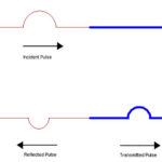
A: RF-system performance has always been concerned with efficient transfer of power between stages; this is not only for “green” power-saving reasons but to minimize thermal issues, dissipation, and signal reflections. However, as operating frequencies reach into the tens of gigahertz, the subtleties of impedance measurement and matching become more critical to overall design success and efficiency. Further, the power levels in 4G wireless systems and upcoming 5G wireless systems (and at much higher frequencies) will be lower for many reasons, so efficient transfer of that power will be critical to achieving system-performance objectives.
Q: Any other reasons?
A: Load pull as a concept is not new; it has been known and used for decades. However, it was a difficult test to set up, and the need was not as great as it is now. The rapid growth in wireless at higher and higher frequency has changed that situation. New applications increasingly need the data it provides, while at the same time new instrumentation is making it more feasible to evaluate at these higher frequencies.
It’s the same positive-reinforcement scenario we have seen for so many technical advances: market growth and changes push the demand for new and improved instrumentation, which test and measurement (T&M) vendors see as an opportunity and challenge. In turn, the new T&M units they develop spur further use of the test for which the instruments were developed, thus expanding its use.
Q: What’s the general procedure for making load pull tests and using the results?
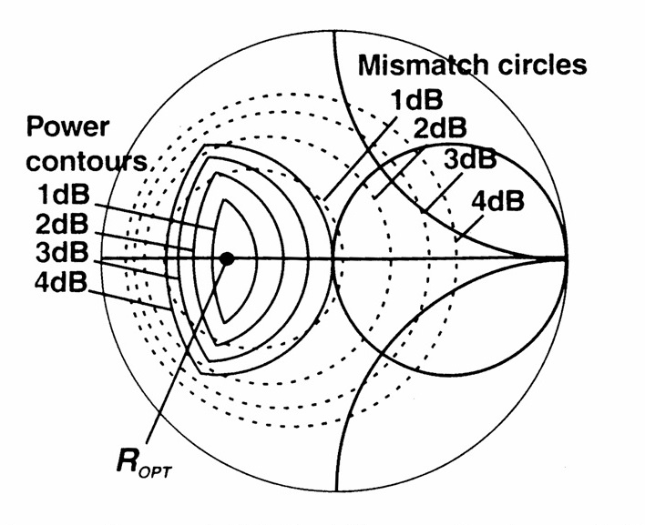
A: From the higher-level perspective, it’s a fairly simple, four-step process: 1) vary the impedance which the DUT sees; 2) measured the key DUT parameters, such as output power, gain, efficiency, or distortion; 3) use these parameters to determine the DUT impedance and the best matching point; and 4) design a matching network which satisfies the matching criteria. Load-pull data allows for the development of matching networks which maximizes power transfer while minimizing reflections and standing waves. The Smith chart developed with load-pull data, Figure 1, shows the optimum matching point Ropt as well as impedances having contours of power losses of 1 dB to 4 dB.
Q: Sounds pretty straightforward, but is it?
A: No, unfortunately it is not that simple: very little in the higher-frequency RF world is easy or direct, even with advanced and suitable instrumentation. The slightest imperfections or mismatch in cables (References 3 and 4), fixturing, and many other factors can result in results which are obviously incorrect or worse, look correct but are not.
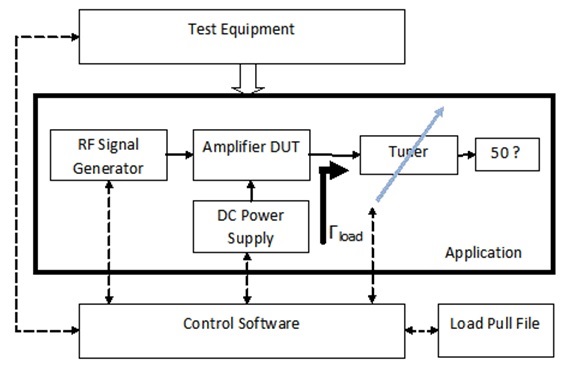
Traditionally, load-pull tests were performed manually, as there was no alternative. In addition to issues of accuracy and validity of the result, these tests were time-consuming and often frustrating. All this has changed, of course, as now there are instruments which are controlled by software and which can automate much of the load-pull testing, Figure 2, and so ease the process somewhat. But it still not a trivial test.
Q: Does the complexity and possibility of invalid results mean we shouldn’t do load-pull tests?
A: If you are doing advanced RF-circuit design, there’s no easy way to avoid load pull. The key to success will be to work with instrumentation from reputable vendors (there are about a dozen among which to choose) with suitable application support in terms of application notes, software and drivers, videos, field engineers, and more.
Most people doing load pull do not need to try to “re-invent the wheel,” as that is better left to the experts who have ways of cross-checking their results as they push state of the art. For example, the engineers and scientists at the National Institute of Standards and Technology (NIST) have extremely clever advanced ways to independently check the results which commercial instruments provide, leading to traceable results and qualification of those instruments. Their expertise extends to highly advanced load-pull testing at frequencies in the 50- to 100-GHz range, where the state of the art is heading.
Part 2 of this FAQ will provide an overview of how a basic load-pull test is set up, and the fundamentally different approaches to measuring the results.
References
- Impedance matching and the Smith chart, Part 1
- Impedance matching and the Smith Chart, Part 2
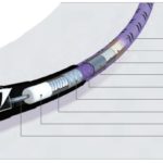
- Microwave/Millimeter Wave interconnects, Part 1: Coaxial cables
- Microwave/Millimeter Wave interconnects, Part 2: Connectors and cable assemblies
- A Beginner’s Guide To All Things Load Pull
- Power amplifier design and load pull measurements in practice
- Power Amplifier Design 2
- Microwaves 101: Load Pull for Power Devices
- Overcoming the Challenges of mmWave, On-Wafer Load-Pull Measurements for 5G