Cables, connectors, and interconnects (cable assemblies) are essential yet often underappreciated parts of a system design. Even though the popular meme is “everything is going wireless” thus eliminating the need for cable assemblies, the reality is that these assemblies are critical both within circuits at either end of a wireless link or as the only practical way to reliably transfer the data at high speeds, with low BER, and be immune to eavesdropping, in many cases.
Some engineers joke that an interconnect is nothing more than a source of potential trouble between two other potential sources of trouble.
There’s some truth in that, of course, but an interconnect is more than a copper wire surrounded by a shield and insulator. Today’s coaxial cable assemblies are highly engineered from electrical and mechanical perspectives and often include additional outer layers for mechanical, chemical, and other protection. This FAQ will explore the cables (wires) and well as the connectors which complete the cable assembly of the interconnect.
Q: What’s the difference between a cable versus an interconnect or cable assembly?
A: Strictly speaking, the cable is the length of wire (here, coaxial) only. The interconnect or cable assembly is a cable to which connectors have been attached. However, popular usage is not precise – nor does it need to be in many cases – so the term “cable” often refers to a complete cable plus its connectors.
Q: Why use coaxial cables? What’s the alternative to coaxial cables?
A: For all but a very few situations, coaxial cables are used to carry RF/microwave energy from point A to point B at higher frequencies. The only viable alternative for conveying RF power with little loss is a waveguide, a rigid assembly that is much harder to specify, fabricate, and use. It was the only option for many years, and it still is when the power levels are high, at multi-kW and higher levels. But many applications are at much lower power levels under a watt or just a few watts.
Q: What are the dominant trends in coaxial cables?
A: While mainstream applications top out at around 1 GHz, today’s smartphones and other applications operate at 5 and 10 GHz. There are applications that are reaching into the millimeter-wave range (up to 100 GHz), including the emerging 5G wireless standard with operation at 20, 30, and 50 GHz, and auto radars operate at 70-80 GHz. As a result, there’s a need for high-performance coaxial cables for these higher frequencies and shorter wavelengths at a reasonable cost.
Q: Why is it difficult to design and build cables for these higher frequencies?
A: It is due to the laws of physic and Maxwell’s equations. At these higher frequencies, any deviation from theory, however minute, is a detrimental factor. Higher frequencies mean shorter wavelengths, so the cable’s critical dimensions are much smaller, and thus tolerances must be much tighter relative to the size. Some multi-GHz cables now have diameters of just a few millimeters, about ten times smaller than those used at lower frequencies. Aggravating the situation, many of these cables need to be mechanically rugged.
In some highest-performance applications, subtle changes in cable parameters due to flexing, temperature changes, and other “normal” variations will degrade performance. Some vendors offer cables that are specifically designed and manufactured to resist these changes, but at a price; in other cases, such as phased-array radar systems, cables must be matched, so they track and have the same changes with temperature variations.
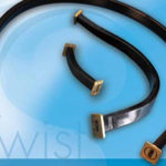
Q: What is the basic construction of a coaxial cable?
A: There are three main components (Figure 1). The center conductor is either solid or stranded wire made of copper with a little aluminum. A dielectric material surrounds this center conductor – usually a blend of plastic and/or foam – which keeps the center conductor isolated, straight, and precisely positioned. The choice of dielectric affects electrical and mechanical performance and is a critical factor.

Some dielectrics can handle higher power, are more crush-resistant, and have more consistent performance across the entire frequency band. Note that some cheaper coaxial cables use low-quality dielectrics and provide marginal, often erratic performance. This may be satisfactory for low-end applications but can cause serious, hard-to-locate problems in applications that require mid-range to superior performance (and there are also many counterfeit or mislabeled cables on the market, too, sad to say).
On the outside of the dielectric is the coaxial cable’s shield, made in most cases of a copper/aluminum foil and/or wire braid. Finally, the overall assembly is covered by a jacket, often PVC, to protect it from the environment and resist abuse, including crushing, twisting, and kinking.
There may be additional outer layers for additional protection; a high-performance cable for multi-GHz operation is a carefully engineered passive component (Figure 2).

Q: What is the impedance of most microwave/millimeter wave cables?
A: The characteristic impedance of a cable is a vital parameter, as all sources and loads must be impedance-matched for maximum power transfer and minimal reflections. Nearly all microwave/millimeter wave cables are designed to provide 50-ohm impedance.
Q: Why 50 ohms?
A: In 1929, researchers at Bell Labs showed analytically that the cable impedance which provided the best power-handling capability was around 30 ohms, but dielectrics which provided this impedance were not available. At the same time, their analysis showed that the best impedance for minimal cable attenuation was 77 ohms. So 50 ohms was a compromise (Figure 3).

In applications such as cable TV, where attenuation is more critical than power handling, 75-ohm cables are used. Another virtue of 75 ohms is that it is easy to match with a standard 300-ohm folded dipole antenna element via a simple 4:1 balun. In most microwave/millimeter wave applications, however, the 50-ohms impedance is used.
Q: What are some key cable-performance parameters?
A: In addition to impedance, factors include:
- Attenuation (also called insertion loss): Loss of power with distance and frequency, measured in dB loss per cable length, such as 30 dB/100 Ft or 10 dB/30m). Attenuation increases as frequency increases;
- Maximum frequency: the frequency at which the cable attenuation is no longer acceptable and is dependent on the application;
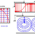
- Shielding effectiveness: the amount of attenuation that the shield provides against electromagnetic energy escaping the shield and is a function of shield design, type, and coverage as well as frequency (Figure 4)

- Power-handling rating: the amount of power which the coaxial cable can handle without breakdown of the dielectric, and can range from a few tens of watts to kilowatts; for many consumer and mass-market applications, the needed rating is very low, on the order of a watt;
- Bend radius: the minimum radius bend a cable can tolerate without any adverse effects on electrical or mechanical performance. Cables are broadly designated as rigid, semi-rigid, and flexible; generally, the less flexible the cable, the more consistent its performance is although it is harder to manipulate and install/remove. Minimum bend radius can be as little as a few millimeters or as high as tens of centimeters, depending on cable diameter, dielectric, and jacketing.
Q: What are some cables in standard or widespread use?
A: For many years, the most widely used cables were RG-58/U and RG/U-8 (a US Government designation: R=Radio Frequency, G=Government, U=Universal Specification). Basic RG-58/U has a solid center conductor, 50-ohm impedance, and 5-mm diameter, with attenuation of 10 dB/100 m at 50 MHz to 70 dB/100 m at 1 GHz. Other variations have a stranded center conductor. The similar RG-59/U has a 75-ohm impedance.
Another cable s RG-8/U. a 50-ohm cable with 10 mm diameter, stranded center conductor, and attenuation of 1.3 dB/30 m at 50 MHz, 7.4 dB/30 m at 1 GHz, and 23 dB/30 m at 4 GHz.
Q: Are these the only coaxial cables in general use?
A: Absolutely not. There are many standard ones, plus numerous proprietary variations offered by vendors which are designed to excel in one or more specifications. For example, the special version may have improved attention, chemical resistance, mechanical strength, or temperature-coefficient ratings.
Therefore, when specifying new cables or replacing existing ones, it is important to understand if a vendor’s version is unique or is interchangeable with others with similar designations.
A microwave/millimeter wave cable by itself is not useful; it needs to be terminated with a connector rather than soldered into a circuit or onto a component in almost every case. Part 2 of this FAQ will complete the interconnection assembly, by looking at microwave/millimeter wave connectors.
References
Microwaves 101, “Why Fifty Ohms”
Belden, Inc., “50 Ohms: The Forgotten Impedance”
W.L. Gore, “Gore Phaseflex”
L-Com, “Coaxial Cable Tutorial”