Low-noise circuitry is critical to the image quality of medical ultrasound, an indispensable diagnostic tool.
Ultrasound technology, a widely used non-invasive tool in medical diagnostics and other applications, has shifted from static to dynamic images and from black-and-white to color Doppler images. These important enhancements are largely due to the introduction of digital ultrasound technology several decades ago. While these advances have increased the effectiveness and versatility of ultrasound imaging, it is equally important for these systems to offer improved image quality via advances in the head-end ultrasound probe and the analog front end (AFE) that drives the probe and captures the return signals.
One of the impediments to achieving this improved image quality is noise; the design goal is to maximize the signal-to-noise ratio (SNR) of the system. This can be achieved in part by addressing noise due to the various power-supply rails in the system. Note that such noise is not a single, simple entity, but instead, it has various characteristics and attributes which determine how it ultimately impacts system performance.
This article will look at the basic operation of an ultrasound imaging system, then focus on different factors that affect image quality, primarily noise from the power supplies.
Basics of ultrasound-based imaging
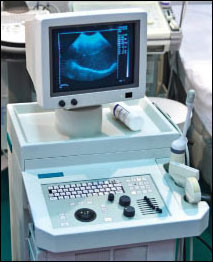
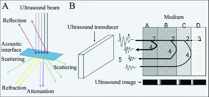
Ultrasound imaging takes a well-known, easily understood physics principle and adds a great deal of sophistication in order to create useful images (Figure 1).
The concept is simple: generate a sharp acoustic pulse, then “listen” for its echo reflection as it encounters obstacles or various interfaces between organs and their differing acoustic impedances (Figure 2). By doing these impulse-return sequences repeatedly, the reflections can be used to create an image of the reflecting surfaces (there’s also scattering and refraction which complicates the situation, but we’ll ignore those).
For most modes of ultrasound, the array of piezoelectric transducers sends a limited number of wave cycles (typically two to four) as a pulse. The frequency of these waves in each cycle is usually in the 2.5 to 14-MHz range. Higher frequencies offer improved resolution but also undergo much higher attenuation as they pass through the body tissues, so recovering a viable signal is very difficult and often obscured by various types of noise. Frequencies around 5 MHz offer are the most-used compromise value between resolution and noise.
The array is controlled via beamforming techniques analogous to a phased-array RF antenna, so the overall ultrasound pulse can be focused and steered to create a scan. The transducer then switches to receive mode to sense the return of the reflected waves from within the body (Figure 3).
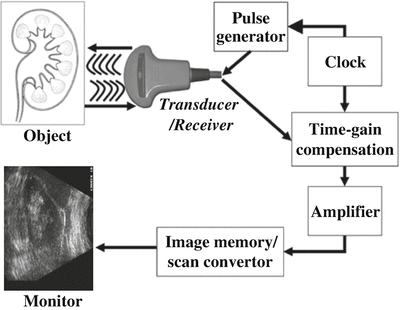
Note that the transmit/receive timing ratio is typically about 1%/99%, with a pulse repetition frequency usually between 1 and 10 kHz. By timing the pulse from its transmission to received echoes and knowing the speed at which the ultrasound energy propagates through body tissue, it is possible to calculate the distance from the transducer to the organ or interface reflecting the wave. The amplitude of the returning waves determines the brightness of the pixels assigned to the reflection in the ultrasound image (after considerable digital post-processing).
It’s never so simple
As ultrasound waves traverse through human tissue and reflect back to the transducer, they interact with tissues and fluids within the body and so are attenuated, lose energy, and are altered in a variety of other ways including a change of direction and even undergoing a change of frequency. An understanding of these interactions is necessary to maximize image quality and correctly interpret the resultant images.
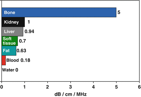
Specific tissues have different attenuation factors (measured in dB/cm/MHz). For example, water has an attenuation factor of 0.0 whereas the kidney has an attenuation of 1.0, and muscle has an attenuation of 3.3 (Figure 4).
When the emitted sound wave pulse travels from one type of tissue to another, some of the energy is reflected at the interface between the tissues. The percentage of energy reflected is a function of the difference in the impedance of the tissues. This impedance is a property of tissue “stiffness” and the speed at which sound travels through the tissue (Figure 5).

This impedance (Z) is a product of tissue density (p) and the acoustic velocity of that tissue (c). It is defined by the formula: Z (dimensioned in “Rayles”) = p (kg/m3) × c (m/s) (Note: 1 rayl — short for Rayleigh — is a unit of acoustic impedance and is equal to one pascal-second per meter (Pa × sec/m) or, equivalently, one newton-second per cubic meter (N × sec/m3)).
If two adjacent tissue surfaces have only a small difference in their acoustic impedances, very little energy will be reflected, which is challenging for imaging clarity. Conversely, if the surfaces have a large impedance mismatch, a greater fraction of the energy will be reflected, and image clarity will be enhanced. Note this energy-reflection and impedance scenario is very similar to what occurs when electromagnetic-wave energy (RF) encounters an impedance transition.
The next part looks at system issues in more detail.
EE World References
Signal generator board produces complex waveforms for ultrasound transducers, medical apps
High-voltage analog switch ICs handle medical ultrasound imaging applications
The Doppler effect: From highly ridiculed to absolutely indispensable, Part 1
External references
National Library of Medicine/IEEE, “Despeckling of Medical Ultrasound Images”
Elsevier/Science Direct, “Performance Enhancement and Analysis of Filters in Ultrasound Image Denoising”
Radiologic Clinics of North America, “The Essentials of Extracranial Carotid Ultrasonographic Imaging”
Maxim/Analog Devices, “Overview of Ultrasound Imaging Systems and the Electrical Components Required for Main Subfunctions”
Analog Devices, “Ultrasound Analog Electronics Primer”
ST Microelectronics, “STMicroelectronics introduces highly integrated 32-channel ultrasound transmitter optimized for handheld scanners”
ST Microelectronics, “Products and solutions for Medical Ultrasound”

