Fiber optic attenuators (optical attenuators) are used to reduce or control the energy of optical signals. They are used in optical communications systems to protect sensitive receivers or to modulate signals and for engineering evaluation, testing, and system validation.
This FAQ reviews the basic operation of optical attenuators, looks at practical applications for optical attenuators, presents several implementations for fixed and variable optical attenuators, and closes with a brief look at zero attenuation loopback optical attenuators.
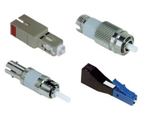
A primary use for optical attenuators is to reduce the energy of optical signals and avoid distortion in an optical receiver that can be caused by a too-strong signal. They are found in fiber optic communications systems in CATV, data centers, and long-distance fiber communications networks. They can also be used for debugging optical power performance. Fixed optical attenuators are available in various package styles to suit the needs of specific applications (Figure 1).
Uses for optical attenuators
There are generally three categories of uses for optical attenuators:
- Reducing power at a receiver. For example, in the case of a fiber optic network, the transmit power level is often based on the distance to the furthest receiver on the line. Too much power can result from a mismatch between transmitters and receivers or result from the use of converters designed to support much longer distances. In each of these cases, an optical attenuator can be embedded in the fiber optic link to consistently reduce the signal power and match the power required by the receiver.
- Fixed optical attenuators are also used for power level margining and system testing. For system testing, the addition of an optical attenuator introduces a known and calibrated amount of signal loss that enables precise measurement of system power levels and performance.
- Variable optical attenuators (VOAs) can modulate and control optical signals. VOAs can be mechanical or solid-state structures. They can be used in LiDAR systems, optical sensing, laser interferometry, test and measurement, and other applications. VOAs can be used for power equalization between multiple channels, power stabilization, turning optical power sources on and off, and for the signal to noise optimization.
Types of optical attenuators
- Displacement optical attenuators – High centering accuracy is required when connecting two sections of fiber optic links to ensure that the signal loss at the interface is minimal. Controlling the centering accuracy enables the attenuation at the interface to be controlled. Displacement optical attenuators use precise misalignments to control the attenuation level. These attenuators are designed using lateral displacements and axial displacements.
- Lateral displacement optical attenuators are fabricated at the micron level of precision and are limited to fixed attenuators. In these attenuators, the fibers are bonded in a lateral or off-axis. displacement configuration. These attenuators can have return losses over 60 dB.
- Axial displacement optical attenuator keeps the fibers centered on each other but bonds/places them a certain distance apart. Axial displacement technology can be used for fixed and variable optical attenuators.
- Thin film optical attenuator uses a metal film vapor deposited to the end of the optic fiber to provide attenuation. The intensity of the reflected light is related to the film thickness. In its simplest embodiment, thin film technology produces fixed optical attenuators. However, suppose a series of metal films with different thicknesses are inserted obliquely. In that case, the intensity of the reflected light can be controlled, resulting in a series of different attenuations and a step variable attenuator.
- Attenuation piece optical attenuators use materials other than thin films to control the attenuation of the light transmission. These optical attenuators can be designed for fixed or variable attenuations.
MEMs VOA
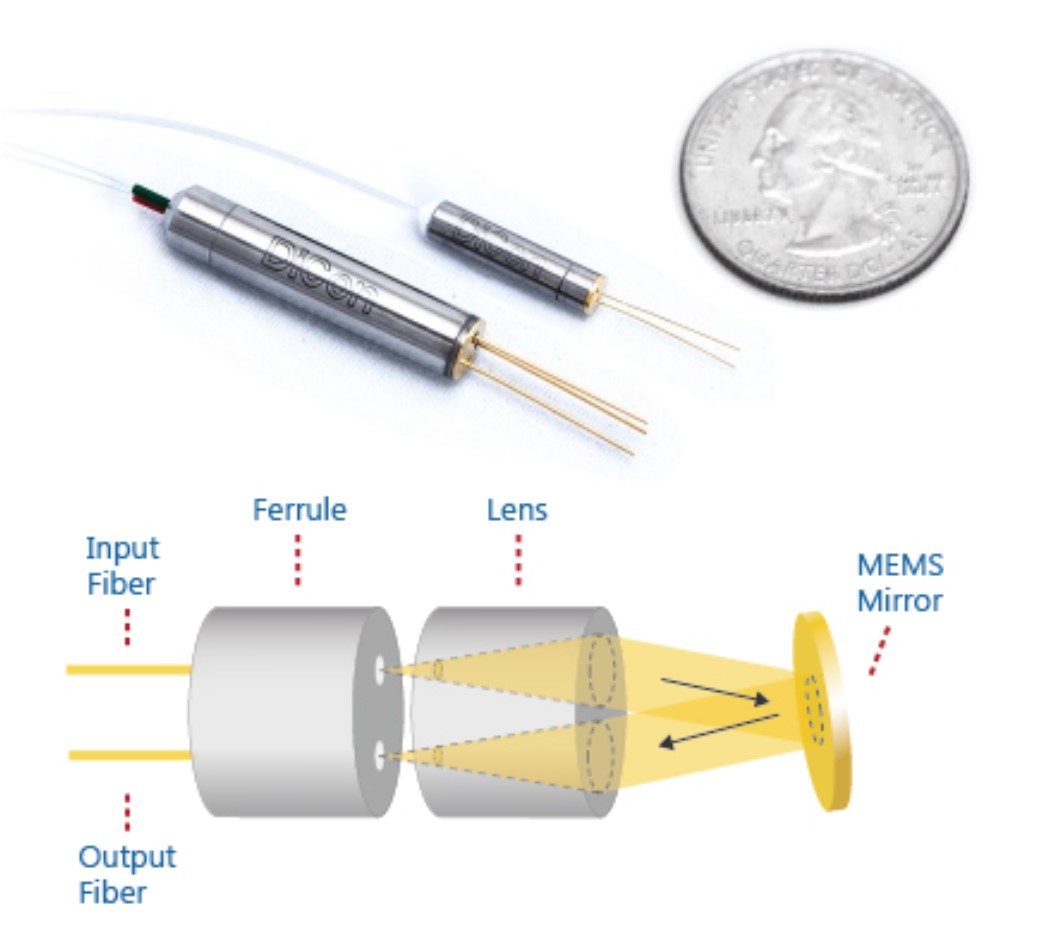
Microelectromechanical systems (MEMS) technology can be used to design VOAs. MEMS mirrors collect and collimate (align) the light from an input fiber, then reflect a precise amount of that light to the output fiber. MEMS VOAs use controlled misalignment to provide precisely managed attenuation levels (Figure 2). MEMS mirrors are highly stable and reliable. By adjusting the drive electronics, MEMS-based VOAs can be customized for a range of system and test and measurement applications.
Because of their small size, up to eight MEMS VOAs with their control electronics can be mounted into a single module. The module can have an I2C or RS-232 control interface. In addition, tap detectors can be added to the outputs of the individual VOAs to support power monitoring. When the power monitoring information is integrated into a closed-loop control scheme, the module can be used as a dynamic power equalizer where the tap power readings provide balanced and constant output power from the individual VOAs. Adding a wave division multiplexing (WDM) filter to the tap detectors can enable multiplexing or demultiplexing of up to four 100 GHz optical channels with power equalization.
ND filter VOA
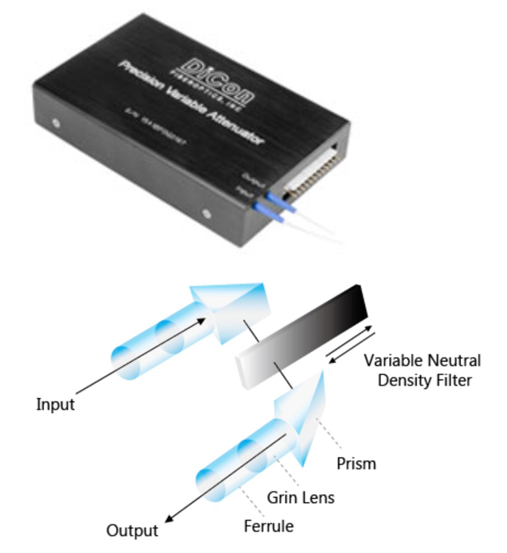
Precision VOAs are available that use a neutral density (ND) filter placed in the light path. The ND filter varies in attenuation from very little attenuation to a large amount of attenuation from one end to the other. A precision stepper motor is used to move the ND filter to the needed position for a precise level of attenuation (Figure 3). ND VOAs are well suited for multimode fiber applications. The ND filter attenuates all modes equally and produces linear response and stable operation.
Inorganic optical crystal VOA
Replacing the moving parts in MEMs and ND filter VOAs with a high-speed inorganic optical crystal filter produces a VOA with sub-millisecond response times, high reliability, and an operating temperature range from -50 to +90 °C. An electric field inside an inorganic optical crystal controls the attenuation level. Drive compensation can be added, making the operation of these VOAs highly stable against a range of environmental conditions. Using a basic integrated electronic driver, the VOA can be controlled by a low voltage signal up to 150 kHz. When operated with full attenuation, this VOA can switch at a fixed 5 MHz frequency. The device can support modulation up to 500 kHz with partial attenuation levels. Their combination of fast switching and environmental ruggedness makes these VOAs suited for mission-critical optical switching applications.
Loopback attenuators
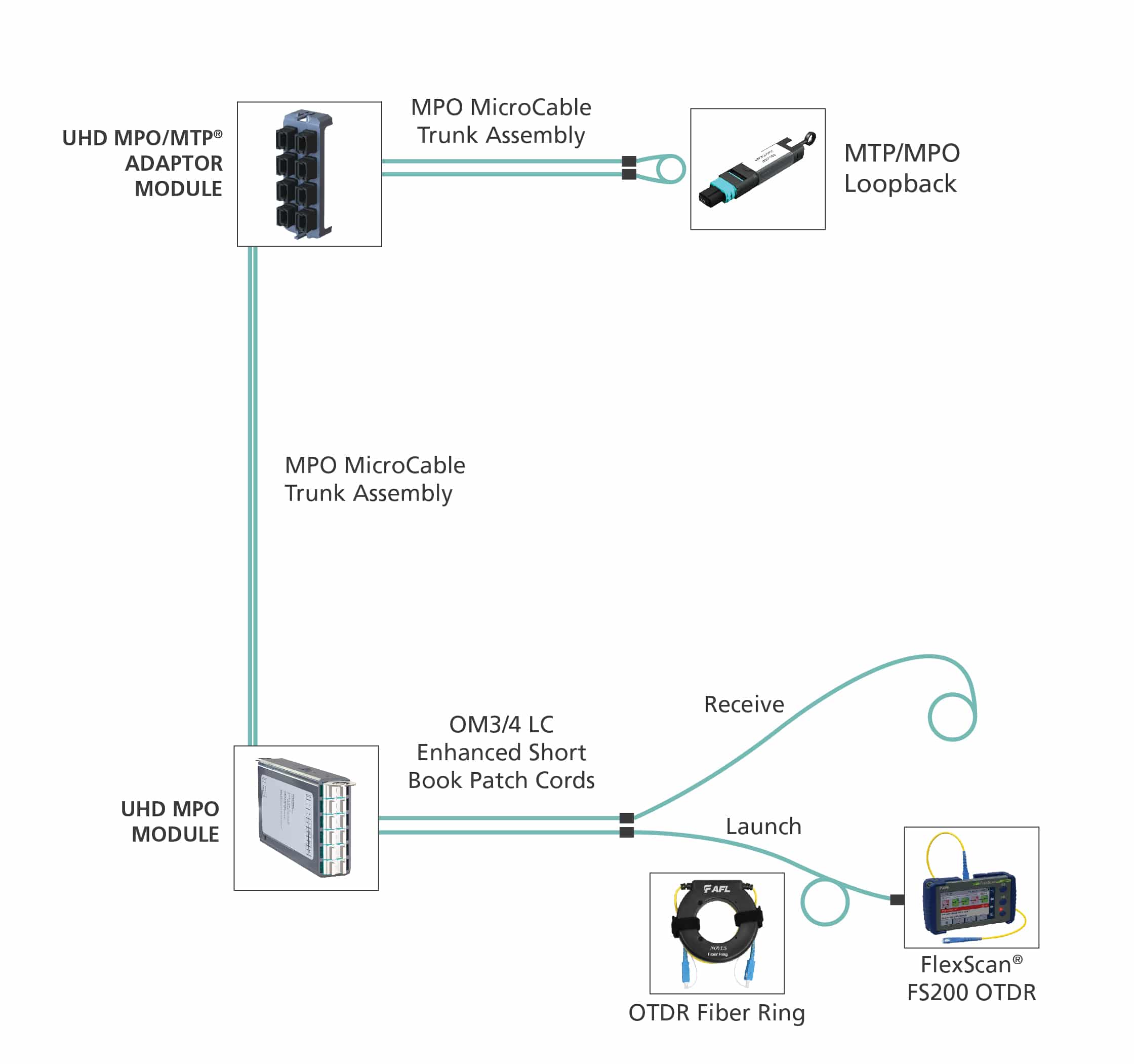
A loopback fiber optic attenuator should have zero attenuation and is designed for routing a signal back to its source without modification. Loopbacks are used for testing, engineering, and the burn-in of boards or other fiber optic equipment. They are used in telecommunications installations and data centers to test the quality and stability of a fiber optic signal path and ensure its operation is error-free. Loopback testing can be performed on the equipment interface or extended to assess the performance of a complete cable installation, feeding the signal to the far end of the installation and back to the starting point (Figure 4). This can be especially important when testing advanced fiber optic ports like those with 40G QFSP+ or 100G CXP/CFP interfaces. Loopbacks tend to be purpose-built and designed to support specific configurations like 8 fiber, 12 fiber, and 24 fiber, multi-fiber push-on/multi-fiber termination push-on (MPO/MTP) connectors with several fiber configurations as required by the interface to be tested.
Summary
Fiber attenuators are important components in communications networks, data centers, and other applications. They are used for engineering evaluation, testing and device, system qualification, and modulating optical signals. Some can also be used for multiplexing and demultiplexing high-speed optical channels. A wide range of technologies can be used to fabricate both fixed and variable optical attenuators. Loopbacks are specialized fiber attenuators with zero attenuation used in telecommunications installations and data centers to test the quality and stability of a fiber optic signal path and ensure its operation is error-free.
References
Basic Understanding of Attenuators, Utmel Electronic
High-Speed Variable Fiber Optical Attenuators, Agiltron
The Ultimate Guide to Fiber Optic Attenuators, FS
Variable Optical Attenuators, DiCon Fiberoptics
What is a Loopback? AFL Hyperscale
What Is Loopback Cable And How to Use It? FS