Using laser-sourced light beams rather than wireless RF to link spacecraft with Earth offers the possibility of a significant increase in data rates. Still, there are significant technical challenges to the concept.
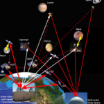
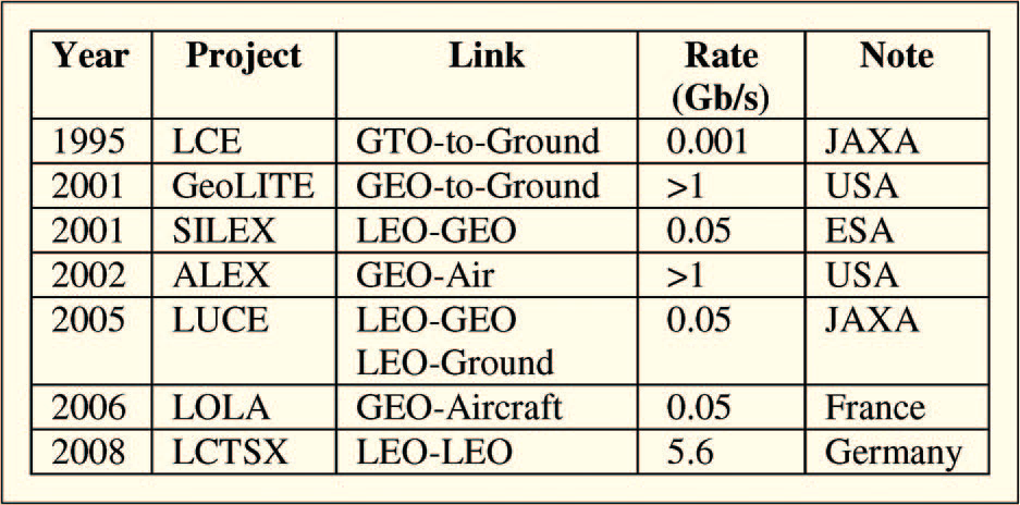
The previous part of the article established the need for higher-speed data links to spacecraft and their missions and looked at some of the issues via optical links. This part looks at one ambitious project in detail and also calls out some other ones. Proof-of-concept optical links have been tested between Earth and moon, between orbiting satellites, and between orbiting satellites and Earth (Figure 1).
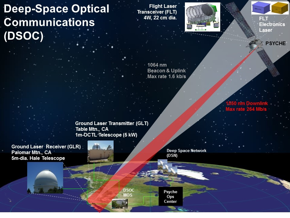
The spacecraft will be launched in the summer of 2022 to asteroid 16 Psyche, a distinctive metal asteroid about three times farther away from the Sun than is the Earth (that’s three astronomical units or AU, where 1 AU is the distance from the Earth to the Sun). The planned arrival of the probe at the main belt asteroid will take place in 2026. Presently, the various pieces are being tested and integrated into a deep-space worthy Flight Laser Transceiver (FLT), with implementations that will advance this mode of communications to Technology Readiness Level (TRL) 6. (Reaching a TRL 6 level equates to having technology that is a fully functional prototype or representational model.)
The optical hardware on the mission is based on a 22-cm diameter DSOC Transceiver. It is designed to provide a bidirectional optical link between a spacecraft in the inner solar system and an Earth-based optical ground station. This design, optimized for operation across a wide range of illumination conditions, is focused on minimizing blinding from stray light, and providing reliable, accurate attitude information to point its narrow communication beam accurately to the future location of the ground terminal.
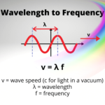
The transceiver will transmit in the 1550-nm waveband and receive in the 1064-nm waveband and uses a common path for propagation among transmit, receive, and pointing-verification optical channels to maintain precise alignment among its components and to naturally correct for element misalignment resulting from launch or thermal element perturbations. The primary goal is to increase data rates by 10 to 100 times but to do so without increasing the mission “burden” of mass, volume, power, and spectrum.
Link difficulties in deep-space optical communications increase roughly with the square of the distance. For DSOC, the signal strength decreases by about 30 dB compared to a comparable optical ink at a lunar distance. The quantitative objective of the DSOC in this mission is to achieve a figure of merit of between 5 and 18 for the achieved data Mbps value times the square of the AU distance (Mbps × AU2).
Building it
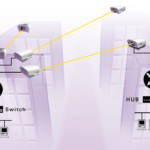
The DSOC mission will simultaneously use two ground stations. The laser beacon to DSOC will be transmitted from JPL’s Table Mountain Facility located near Wrightwood, California, in the Angeles National Forest. DSOC’s beaming of data from space will be received at a large aperture ground telescope at Palomar Mountain Observatory in California (Figure 2).
Achieving initial alignment between optical transmitter and receiver is a major challenge and a multistep process. First, a conventional RF link is used for coarse alignment (“coarse” is a relative term here, as this is a still fairly accurate alignment – but not enough). This is followed by an optical “beacon” signal, making it easier to identify and correlate the source emissions. Finally, the actual data signal is transmitted.
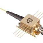
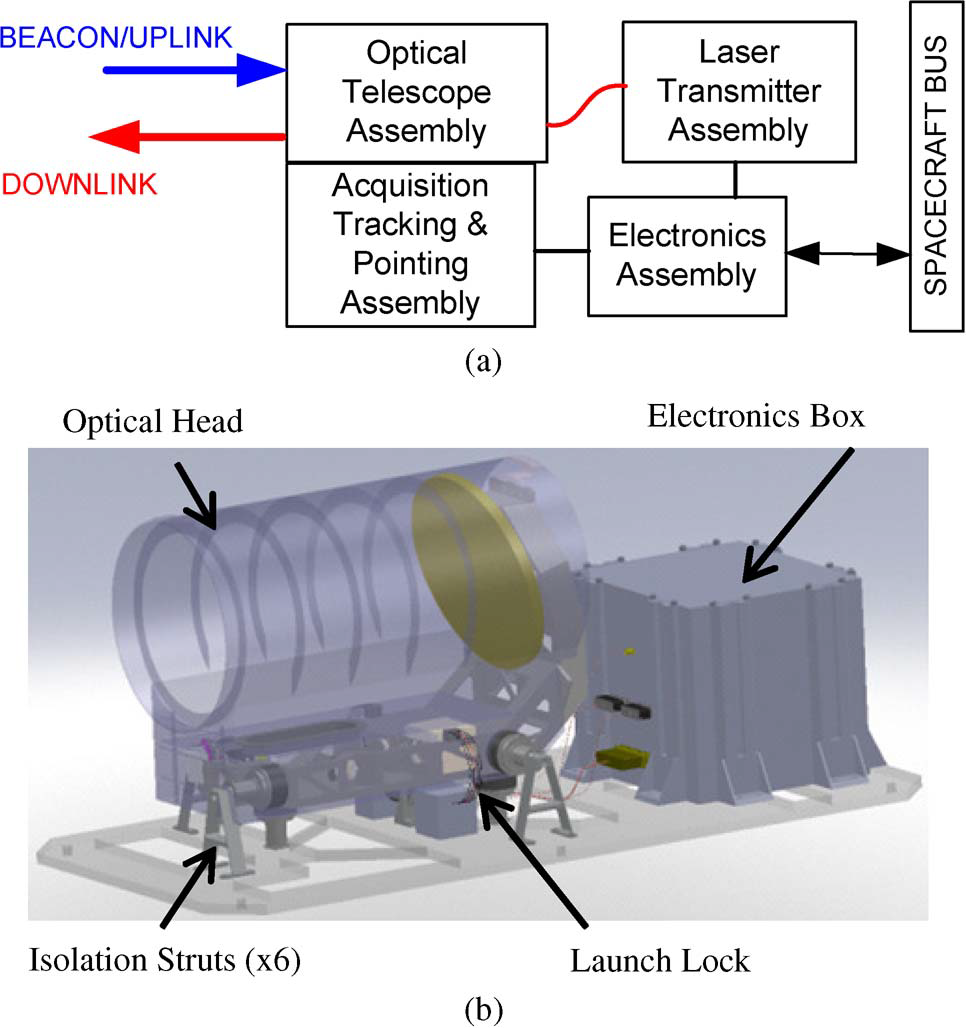
This DSOC world is one in which even single photons are meaningful. The receiver is designed to capture and verify individual photons at the correct wavelength. The system in the spacecraft terminal is a complex assembly of optical elements, electro-optical components, and electronics (Figure 3 and Figure 4).
The average output power for the spacecraft laser is typically between 1and 20 W, with peak power on the order of hundreds of watts to over 1 kW. Typical pulse widths range from subnanoseconds to several nanoseconds, and pulse repetition frequencies are between 0.1 MHz to hundreds of megahertz, with laser pulse widths of approximately 50 picoseconds.
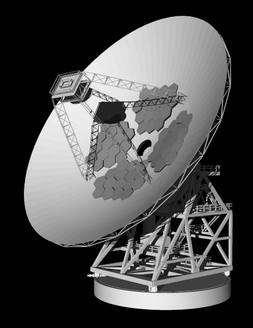
Even though the ground station has far fewer mass, power, and other constraints when compared to the system in the spacecraft, there are still major challenges. One is how to ensure that the ground-based RF link and the optical link are aligned. The solution is not to build another parabolic optical reflector (analogous to the RF antenna) and attempt to coordinate the two instead of “piggyback” on the RF antenna.
To achieve this, specially designed, aligned, and actively managed mirrors are placed near the center of the parabolic RF antenna (Figure 5). This optical reflector portion is built of four pods, each with 16 hexagonal mirrors. The optics must dynamically be adjusted to compensate for thermal and atmospheric aberrations and distortions. RF energy capture is lost as some of the dish’s surface is lost for RF use, but this is deemed an acceptable tradeoff.
The above is just a brief overview of the realities of the straightforward idea of using lasers instead of RF as the communication link between Earth and spacecraft. Still, it is reality a very complex problem with many constraints and challenges. More information about DSOC, including link budgets, bit error rates (BER) versus signal/noise ratio (SNR), and additional system analysis is in the References.
Other optical-link projects
The DSOC is only one of several projects underway and perhaps the most ambitious one. But all of them have challenges. Among the other NASA projects are:
- Science Enabling Technologies for Heliophysics (SETH), a small satellite mission concept using a Compact Laser Communication Terminal (CLCT) to demonstrate high-rate optical communications from deep space. This cutting-edge technology will support the Helio Energetic Neutral Atom (HELENA) heliophysics instrument that demonstrates solar energetic neutral atom (ENA) and space weather observation capabilities to support NASA’s Moon to Mars exploration initiative. SETH is planned to demonstrate data rates of at least 10 Mbps from 0.1 AU.
- The Laser Communications Relay Demonstration (LCRD) which will be NASA’s first two-way optical communications relay system and showcase the unique capabilities of optical communications. LCRD will demonstrate data rates of 1.2 gigabits/second. Missions in space will send their data to LCRD, functioning as a relay satellite, transmitting it down to ground stations in Haleakalā, Hawaii, and Table Mountain, California.
LCRD’s first user will be a terminal on the International Space Station. However, before mission support, LCRD will spend two years testing its optical capabilities with various experiments, refining the technology. LCRD will be hosted on a U.S. Department of Defense Space Test Program Satellite 6 (STPSat-6) in geosynchronous orbit (about 22,000 miles) around Earth.
- In October 2013, NASA’s Lunar Laser Communication Demonstration (LLCD) transmitted data from lunar orbit to Earth at a rate of 622 Megabits-per-second (Mbps) with an error-free data upload rate of 20 Mbps – that download rate is more than six times faster than previous state-of-the-art radio systems flown to the moon. The laser beam was transmitted the 239,000 miles from the primary ground station at NASA’s White Sands Complex in Las Cruces, N.M., to the LADEE spacecraft in lunar orbit. This breakthrough technology has a laser-based space terminal that is half the weight of a comparable radio-based terminal while using 25 percent less power.
There are other optical-link projects underway as well.
Conclusion
It seems like a simple, obvious idea: leverage the enormous available width and associated bandwidth of the optical spectrum. Using lasers and photons rather than RF for links to both close-to-Earth satellites and far-traveling spacecraft would potentially allow achievement of data rates which are far faster than those which standard, albeit highly refined, RF links can ever offer.
But the reality is that many component-related and system-level issues must be understood, addressed, and resolved so the optical link will be a viable and better option. Overall, there has been significant progress with many trials and tests of components, sub-assemblies, complete systems, and actual flights. It is certainly not easy in any respect, and the difficulties are compounded by the usual issues related to any “hardware” in space with regard to weight, volume, power, reliability, and stress.
Related EE World Content
Free-space optical links, Part 2: Technical issues
Free-space optical links, Part 3: Standard units
Free-space optical links, Part 1: Principles
Phased-array antennas optimized for satellites, space vehicles
Challenges in designing electronics for satellites
Infographic: How Are Satellites Shaping Our World?
External References
General
- NASA, “NASA Laser Communications Innovations: A Timeline”
- NASA, “Laser Communications: Empowering More Data Than Ever Before”
- NASA, “NASA Taking First Steps Toward High-speed Space ‘Internet’ “
- NASA, ”Lasers Light the Way”
- NASA, “Mars Reconnaissance Orbiter Press Kit”
- Chalmers University of Technology, “One photon-per-bit receiver using near-noiseless phase-sensitive amplification”
- Chalmers University of Technology, “Supplementary information for One photon-per-bit receiver using near-noiseless phase-sensitive amplification”
- NASA, “Pysche”
- NASA, “Pysche Mission Website”
DOSC
- Proceedings of the IEEE, “Deep-Space Optical Communications: Future Perspectives and Applications”
- NASA, “Lighten Up” – Deep Space Communications via Faraway Photons”
- American Institute of Aeronautics and Astronautics, “Toward a NASA Deep Space Optical Communications System”
- NASA, “Status of NASA’s Deep Space Optical Communications Technology Demonstration”
- Wikipedia, “Deep Space Optical Communications”
- SPIE, “Discovery deep space optical communications (DSOC) transceiver”
- NASA, “Deep Space Optical Communications (DSOC)”
LCRD
- NASA, “NASA’s Next Laser Communications Demo Installed, Integrated on Spacecraft”
- NASA, “Laser Communication Relay Demonstration (LCRD)”
- NASA, “Integrated LCRD Low-Earth Orbit User Modem and Amplifier Terminal (ILLUMA-T)”
SETH
- American Institute of Aeronautics and Astronautics, “SETH Technology Demonstration of Small Satellite Deep Space Optical Communications to aid Heliophysics Science and Space Weather Forecasting”
LLCD
NASA, “Historic Demonstration Proves Laser Communication Possible”