A combination of optics, lasers, electronics, and combined with advanced physics principles, allows “touch-free” physical manipulation of molecules, viruses, and other nano-sized objects.
Part 1 of this article presented the goals of the optical-tweezer design and some of the reasoning which leads to it. This part continues to build up to a larger, complete system.
The trapping phenomenon is fully explained through the use of Maxwell’s electromagnetic-field equations, quantum physics principles, and some fairly advanced math. However, for cases where the size of the target object is larger than the wavelength of the laser’s output, it can also be described somewhat more intuitively by ray optics (note that for the reverse case, where the object is smaller than the wavelength, Maxwell’s equations are the way to go). It’s not enough to shine a laser at a tiny object since that might just move it along randomly, yet not allow trapping and controlled motion (roughly analogous to pushing on an object that has no front wheels for steering control).
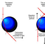
Consider a laser beam focused on a small dielectric sphere or bead. The bead acts like a weak lens, and as the incident light passes through this object. Due to its small size and thusly inherent high numerical aperture, the light is refracted and becomes concentrated into a beam with a tight “waist” and large gradient (Figure 1). The refraction of light by a transparent object results in a change in photon momentum and a corresponding reaction force acting on the object.
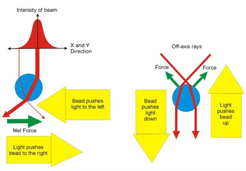
Since photons have momentum, two forces are acting on the bead: an axial scattering force, which is pushing the bead in the direction of incident light, and a radial gradient force pulling the bead in the opposite direction. The refraction of light causes the gradient force as it passes through the bead, with a resulting change in momentum.
Since momentum is conserved, the net change in momentum must be zero, and so momentum must be transferred from the laser beam to the bead in the equal and opposite direction. If the bead is off-axis from the incident beam, it will refract the light such that the gradient force will move the bead back on axis. Since the bead is self-trapped in the laser’s beam, it can then be moved in any dimension by precise steering of the laser output.
There’s an associated problem which the team solved in 1987. The divergence of the incident beam – which is critical to trapping – drops off more rapidly from the maximum value at its center as the target bead gets smaller, and its numerical aperture thus increases. By using a Bessel-focused laser beam, which has an intense center spot and a set of concentric rings rather than a conventional (Gaussian) beam, the diffraction can be controlled. Generating this Bessel beam is fairly easy in principle: just shine the conventional beam through a standard conical lens (called an axicon); you can even buy fiber-optic lasers which come with the axicon precisely centered and glued to the fiber’s end.
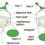
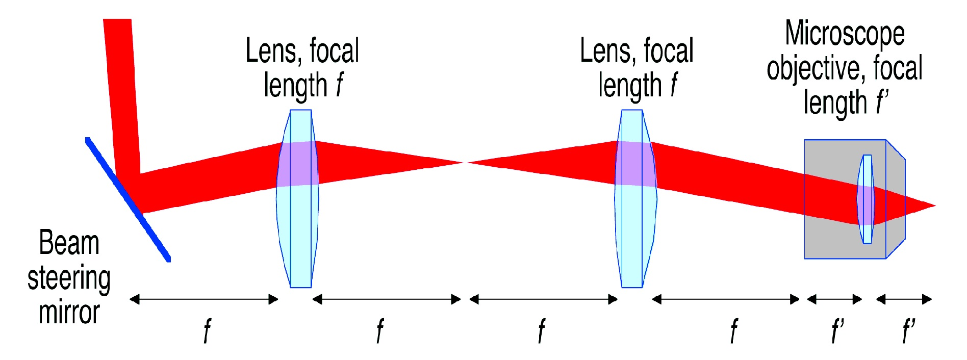
As with all these projects, the brevity of the description of the core of the instruments can easily obscure the fact that there is a great deal more to the trapping and tweezing process. For the optical tweezer, the laser needs additional lenses plus a way to merge the laser beam with an optical-imaging subsystem so the user can see what’s going on (Figure 2).
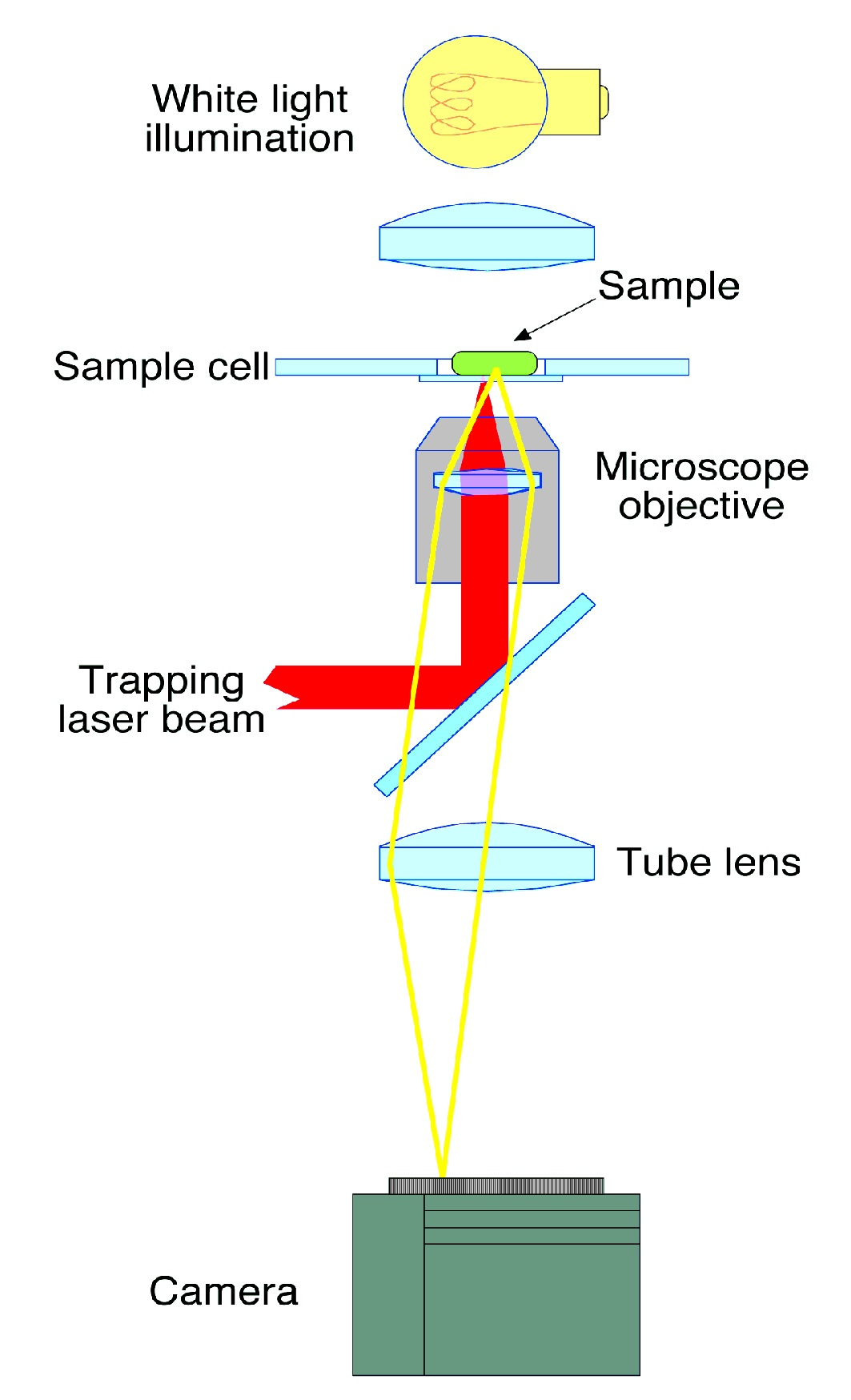
Also, as with nearly all optical systems, there’s a need to ensure proper alignment and facilitate adjustment for inevitable imperfections, no matter how much care is used in fabrication and set up. The early design used a multiple-lens arrangement to enable near-perfect collimation (Figure 3). This arrangement is now automated with computer control of lens movement to produce an optimum light path.
Part 3 of this article will look at a complete system, possibilities for building your own, and extensions to the basic optical tweezer.
EE World References
Assembling Micro-Components With Laser Tweezers
Nanotweezer Is New Tool To Create Advanced Plasmonic Technologies
A Levitated Nanosphere As An Ultra-Sensitive Sensor
The difference between scanning electron microscopes and tunneling scanning electron microscopes
The instrumentation of nanotechnology
Magnetic resonance imaging (MRI), Part 1: How it works
MRI, Part 2: Historical development (and lawsuits)
Nanowires As Sensors In New Type Of Atomic Force Microscope
Atomic Force Microscope Reveals Chemical Ghosts
External References
- Ashkin, A., “Acceleration and Trapping of Particles by Radiation Pressure,” Physical Review Letters, 1970. 24(4): p. 156
- Justin E. Molloy and Miles J. Padgett, “Lights, action: optical tweezers,” (Contemporary Physics), 2002, volume 43, number 4, pages 241 to 258.
- Trygve Bakken & Adam Koerner, “Optical Tweezers,” University of California at San Diego, Biophysics Lab, June 2009.
- “Optical trapping: How does it work?, University of St. Andrews, Scotland.