
Resistance soldering is an alternative to conventional “pencil” soldering iron, which offers unique capabilities.
Resistance soldering is an easy-to-use alternative soldering technique that’s been available for decades and offers many benefits, although it cannot always be used when soldering is required. It leverages the well-known principle of electrical self-heating (I2R dissipation) to create a localized “hot spot,” which is hot enough to melt the solder and make a high-quality, reliable solder connection.
The solder itself is the same type as used for pencil-style soldering irons. In some ways, resistance soldering is a small-scale version of electric-spot welding.
Typically, a standard AC-line voltage source goes through a step-down transformer to provide a low-voltage, high-current output of 10 amps. The amount of current required is a function of the resistance and the subsequent heating of the item to solder. This high current generates a large amount of heat in a tiny area, allowing for delicate soldering of small or closely spaced components.
The operator places the tweezer-like electrical probes of the handpiece — often made of graphite — on either side of the item or connection to be soldered, then activates the current flow with a foot-operated switch.
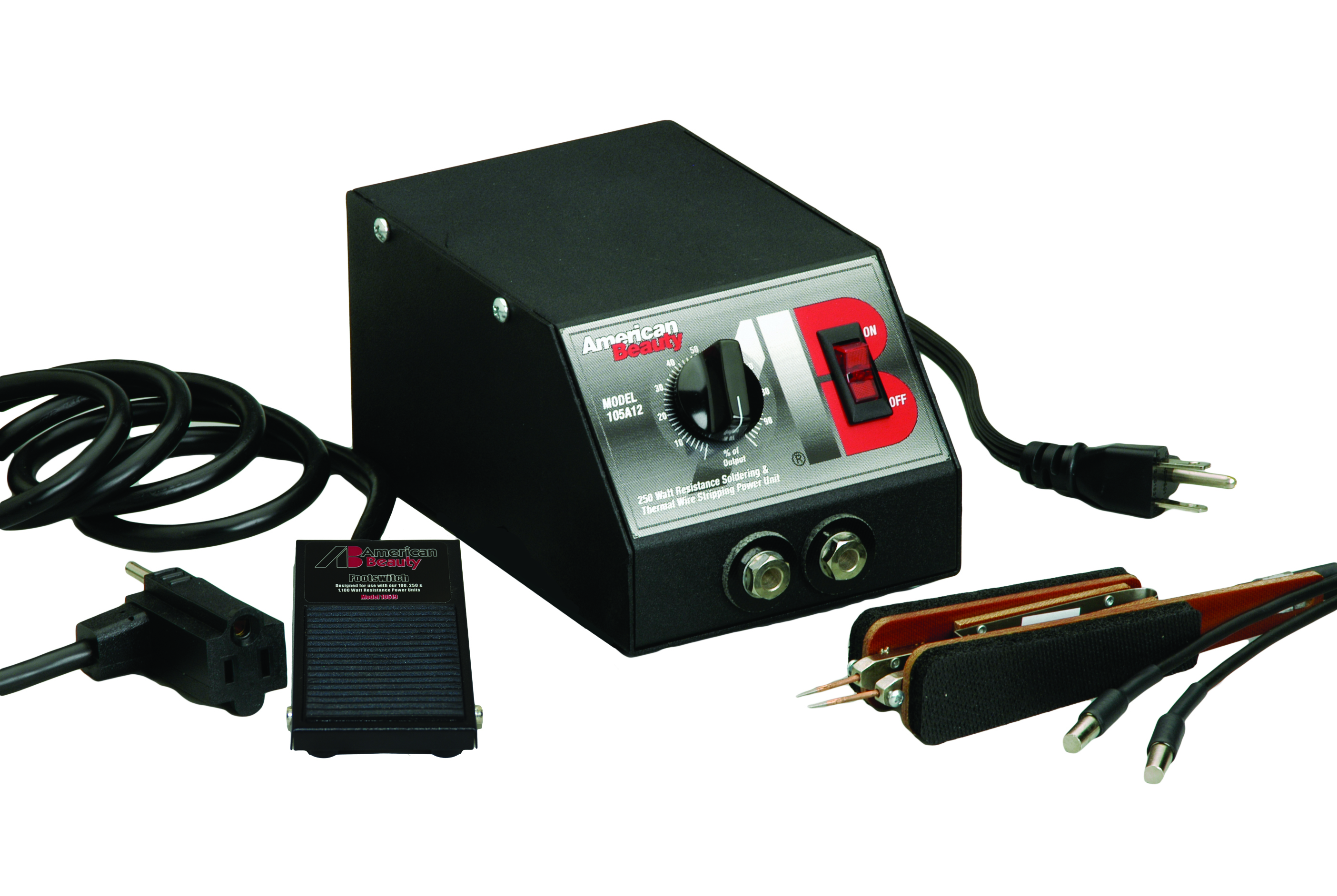
A typical resistance-soldering system is the American Beauty Tools Model #10502 light-capacity tweezer-style unit (Figure 1). This unit can deliver up to 250 watts at 2.8 VAC (not a typo — it’s at just a few volts) to the connection to be soldered.
Operation is simple: the current from the system is applied across the joint via the pair of tweezers of the handpiece, with the tweezer’s tips positioned to “straddle” the connection to be made.

How it works: the operator steps on a foot pedal, current flows between the tips, the joint heats, the operator applies the solder, lets it melt, and releases the foot pedal. The whole sequence takes a few seconds. The heat, which might otherwise damage or melt adjacent components or materials, is nearly non-existent. As the applied voltage across the tips is low — on the order of a few volts — there’s no danger of shock to the user or damage to nearby components.
The handpiece and its tweezer area are critical parts of the system’s flexibility, performance, and convenience. The tip of a pencil-style soldering iron must touch the joint to be soldered with sufficient thermal-contact area. This contact area enables adequate heat transfer to the joint to melt the solder (basic soldering rule: the joint to be soldered must melt the solder, not the soldering unit point itself). However, providing sufficient surface-contact area is a challenge in tight spaces or with small components.
In contrast, the tweezers of the resistance soldering system direct the flow of current, which is more precisely locatable and efficient in tight situations. Further, vendors offer these handpieces in multiple sizes to handle different soldering situations and spaces.
There are some unique attributes and advantages to resistance soldering:
- Heating is instantaneous and confined to solder connection, and the process is generally much faster than soldering with a traditional iron.
- The handpiece cools extremely fast, reducing the risk of serious operator burns. Heat is only generated during the soldering operation, so there’s no chance of bumping into an iron that’s hot and sitting idle near the operator.
- Resistance-soldering electrodes and elements last several times longer than traditional soldering iron tips, reducing replacement costs.
- The footswitch eases set-up and fixturing, leaving a free hand for the operator.
- There is energy and savings in operating costs since the unit is only turned on when required and not left “idling” and hot as with most low-cost soldering units.
- The resultant heat is concentrated and controlled, minimizing collateral heating and damage.
Applications and variations
Resistance soldering has several applications aside from soldering typical electronic components. For example, when soldering a power-feed wire to the side of the tiny rail of a model railroader, a standard soldering iron will likely melt the adjacent ties of the rail. In contrast, resistance-soldering heat is localized and only heats the connection point.
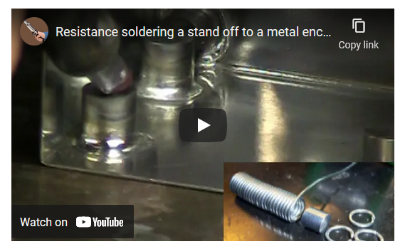
There are many resistance-soldering tutorials and example videos online, such as this one showing it being used to solder a standoff to a metal enclosure (Figure 2).
The applications for resistance soldering go well beyond electrical and electronic connections. It can be used for stained-glass projects, sealing small holes in gutters, model building, and certain jewelry and crafts.
As with any system, resistance soldering has potential drawbacks. Among these are that the up-front cost of the equipment (around $500) is pricier than a typical traditional soldering iron and somewhat higher than a temperature-controlled conventional soldering station. Also, the simple soldering pencil is more portable. Resistance soldering is not an ideal fit for all components, particularly if accessibility is a concern.
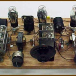
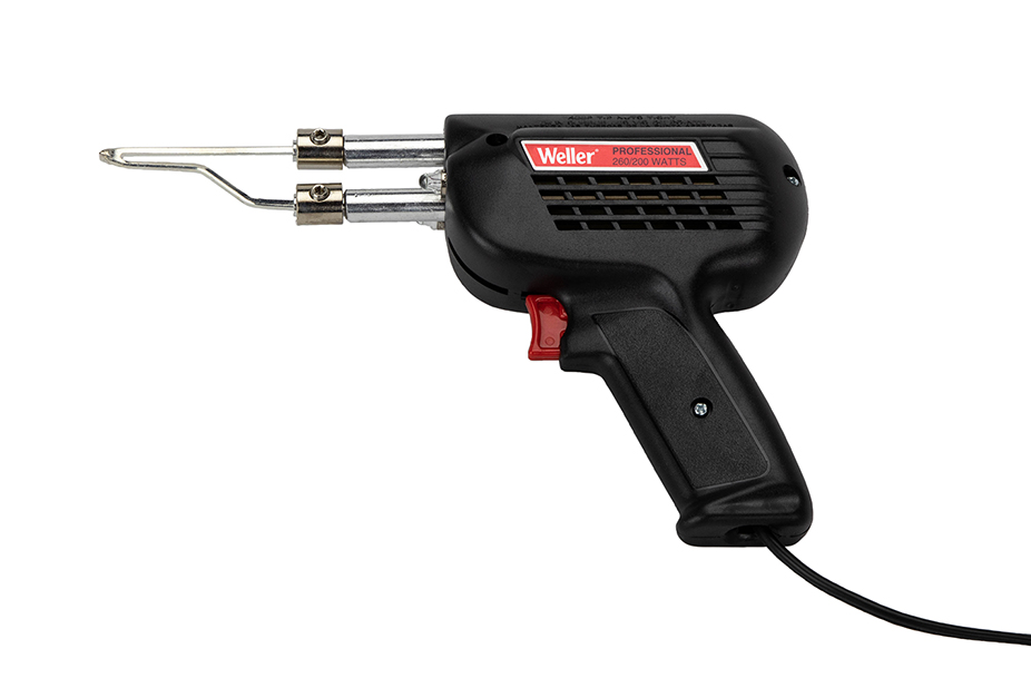
Although not recommended, the relatively safe nature and low voltage of the construction of a resistance-soldering also lends itself to do-it-yourself systems using a transformer or battery charger. Ironically, an old-fashioned but widely used soldering gun can be used as a resistance-soldering unit, although with substantial weight (Figure 3).

This gun is a specialized version of a resistance-soldering system using a hybrid operating scheme. It passes current through its low-resistance metal tip, transferring its heat to the joint to be soldered, as with a conventional pencil unit.
So, by cutting off the tip of the tip, the unit is easily converted to a resistance soldering unit as the cut-off ends act as the workpiece tweezers. Of course, this arrangement offers less convenience with more weight than a power unit with a separate handpiece and tweezers.
Conclusion
Resistance soldering is not a panacea to soldering issues and does not replace PC board wave, reflow, or other “mass” soldering systems. Nonetheless, it’s an effective alternative to conventional soldering irons and offers some benefits in terms of convenience, localization, and control.
Related EE World Content
A Reliable Alternative to Manual Soldering
Soldering tips for newbies
Do You Really Need Soldermask And Silkscreen For PCB Design?
Reasonably priced solder stations – forum member reviews
References
- About Mechanics, “What is Resistance Soldering?”
- American Beauty Tools, “Resistance Soldering”
- American Beauty Tools, “American Beauty Resistance Soldering Systems”
- Model Train Forum, “Resistance Soldering?”
- Engineering Choice, “What Is Soldering?- Types And How To Solder”
- Model Railroader, “Resistance Soldering”
- NMIA, “Build your own resistance solderer”
- The World of Rail, “Resistance Soldering Unit”
- National Model Railway Association, “Making a Low-cost Resistance Solderer”