
Part 1 of this FAQ looked at two basic receiver architectures: the tuned radio frequency approach (now largely obsolete due to performance shortcomings), and the superhet design which has been used with great success for about 100 years. Part 2 looks at two other architectures – the zero-IF design and the software-defined radio – which have become viable alternatives to the superhet in some situations, due to new developments in components and circuits.
Q: What is a zero-IF receiver design?
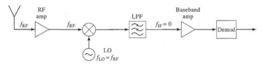
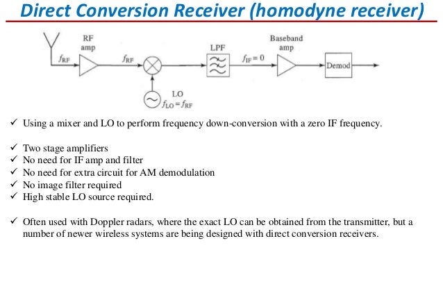
A: Zero-IF, sometimes called a direct conversion or homodyne architecture, uses a local oscillator which is set equal to the desired carrier frequency being tuned, or very close to it, Figure 1. This reduces the IF frequency to zero or near zero, rather than standard values such as 455 kHz.
Q: What are the advantages of the zero-IF design?
A: The advantage of this direct-to-baseband conversion that it eliminates some of the IF-related circuitry (especially filtering), and also avoids the problem of “image frequencies” which are an inherent part of the mixer output in the standard superhet and must be carefully managed and filtered. The zero-IF receiver architecture is also attractive because it can ease demodulation of very wideband RF signals.
Q: If zero-I F eliminates circuitry and has other virtues, why isn’t it used more often?
A: Zero-IF places extreme demands on both the LO performance and the mixer performance. Any instabilities or imperfections in the LO, and any DC offsets or imperfections in the mixer, quickly corrupt the resulting zero-IF output and so result in poor system performance. The approach also has issues of achieving sufficient dynamic range, which is a factor in most received wireless signals.
Q: What is software-defined radio?
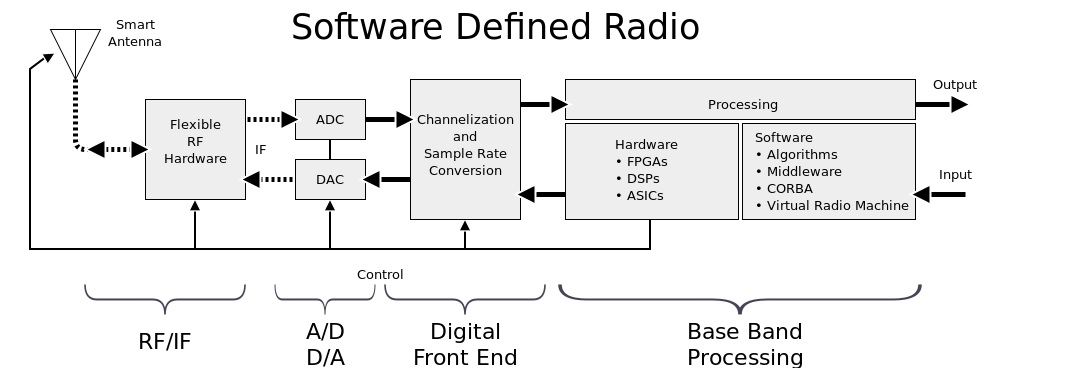
A: SDR is a radically different approach to tuning, demodulating, and decoding a received signal. SDR does not bring the modulated carrier signal down to baseband via analog circuitry and IF stages, or directly bring the signal of interest down to baseband as is done in the zero-IF approach. Instead, SDR uses fast, precise, high-resolution analog/digital conversion of the original received signal band – not just the single desired signal – at its original carrier frequency, Figure 2. (Note that in some cases, the received signal band is first downconverted to an intermediate fixed IF to reduce digitization speed and bandwidth demands, and the SDR operates on that IF signal).
Q: What happens to all this digitized information?
The huge stream of digitized data which results is then processed by various sophisticated algorithms in a processor (almost always an FPGA) to select, extract, and demodulate the desired signal from the mass of data.
Q: What are the advantages of SDR?
A: In a word: flexibility. With SDR, the same circuitry can be used to recover signals across a wide band of the spectrum, and with different bandwidths and modulation schemes. All the signal processing is done by software, which means that almost all performance parameters and considerations are not only programmable but can be changed in real time. As a result, a single hardware design can handle AM, FM, and PM, as well as different data formats and data rates, and more, simply by using different code executing on the SDR receiver.
Q: Where does the SDR architecture have the greatest likely opportunity?
A: SDR is very attractive in military and public safety situation, because it overcomes the interoperability issue. An SDR-based receiver can change “on the fly” to interact with other users who have different signal types, d and formats. Therefore, the problems on one group or team not being able to communicate with another user or set of users can be avoided.
Q: If SDR is so flexible, what are its weaknesses?
A: First, the A/D converters used to digitize the received signal are must provide high conversion resolution (typically, 12 or 14 bits) at high speed and wide bandwidth. Any imperfection in the A/D converter such in inadequate SFDR (spur-free dynamic range), noise, jitter, or distortion, corrupts and becomes part of the data that must be analyzed, which can mislead the algorithms, lead to recovered data errors, or require extra processing. Not only are these converters expensive, but they tend to be power hungry. Further, the FPGA must be very powerful with high MIPS rating and therefore is also costly and a large power consumer. Finally, the software algorithms are complex and can be hard to develop, debug, and verify.
Therefore, the potential flexibility of SDR, and its ability to change and be modified to handle different frequencies, signals and situations, must be weighed against not only potential flaws in code and algorithms, but the high cost in dollars and dissipation of the A/D converter and the FPGA, as well as memory, I/O, and other requisite hardware elements These factors may outweigh the benefits.
References
The Wireless Innovation Forum, “What is Software Defined Radio?”
University of California at Berkeley, “Wireless Lab 1: Software Defined Radio”