• Skip to primary navigation
  • Skip to main content
  • Skip to primary sidebar
  • Skip to footer

Analog IC Tips

Analog IC Design, Products, Tools Layout

  • Products
    • Amplifiers
    • Clocks & Timing
    • Data Converters
    • EMI/RFI
    • Interface & Isolation
    • MEMS & Sensors
  • Applications
    • Audio
    • Automotive/Transportation
    • Industrial
    • IoT
    • Medical
    • Telecommunications
    • Wireless
  • Learn
    • eBooks / Tech Tips
    • FAQs
    • EE Learning Center
    • EE Training Days
    • Tech Toolboxes
    • Webinars & Digital Events
  • Resources
    • Design Guide Library
    • Digital Issues
    • Engineering Diversity & Inclusion
    • LEAP Awards
    • Podcasts
    • White Papers
    • DesignFast
  • Video
    • EE Videos
    • Teardown Videos
  • EE Forums
    • EDABoard.com
    • Electro-Tech-Online.com
  • Engineering Training Days
  • Advertise
  • Subscribe

Do you really need soldermask and silkscreen for PCB design?

January 3, 2018 By Lee Teschler

Duane Benson, Chief Technology Champion, Screaming Circuits

As PCB assemblers, we’ve been asked the question,”Do I really need soldermask and silkscreen?” many times. And, we’ve been asked with good reasons. To us, soldermask protects exposed metal, reduce the chance of shorts and keeps solder where solder needs to be. Silkscreen removes ambiguity, ensuring that parts go where parts need to go, and that they are pointed the way they need to be pointed.

But, that’s just the Screaming Circuits perspective. Right? Doesn’t leaving mask and silk off dramatically reduce the cost? On the surface (pun somewhat intended), leaving off the soldermask and silkscreen seems like it reduces cost. You can buy boards that way for less money. That’s the short answer — and the incorrect answer according to probably all assembly service providers.

If you’re hand building your own boards, it may be a viable option, but it can lead to so many other problems down the road, we recommend always having a soldermask. Always.

Without soldermask, solder can migrate off the pad, on to the traces or down into vias. The amount of solder paste we put down on a surface mount pad is based on making a good solder joint and having solder mask to prevent that migration. Some PC board metal surfaces will corrode if not covered with either solder or solder mask. And it’s a lot easier to short something in operation with all of that extra exposed metal.

assembly drawing screaming circuits
A good assembly drawing format containing reference designators and polarity marks.
What about silkscreen? Shouldn’t all of the automation render the need for silk screen an obsolete requirement? In theory yes. In practice, no. Even though we have a nice set of industry standards, the adoption of those standards is sporadic enough that we simply can’t rely on data to be accurate. There’s still a lot of human work and too much ambiguity due to poor use of standards in marketing.

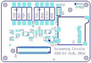
The only exception with silkscreen is having a good assembly drawing. If you have a detailed assembly drawing, with all reference designators, part outlines and polarities clearly marked, you can get away without silkscreen. Some people like to put other information on the board, like instruction or port identifications. In cases like that, all the reference designators can make the board unreadable. If you need that, provide an assembly drawing.

You may also like:

  • edaboard.com
    Analog Top Talks in November on EDABoard.com forums

  • General tips for preventing problems in analog circuits

  • Your Summer Reading List: 16 useful electronics engineering resources

Filed Under: FAQ, Featured, PCB design Tagged With: screamingcircuits

Primary Sidebar

Featured Contributions

Design a circuit for ultra-low power sensor applications

Active baluns bridge the microwave and digital worlds

Managing design complexity and global collaboration with IP-centric design

PCB design best practices for ECAD/MCAD collaboration

Open RAN networks pass the time

More Featured Contributions

EE TECH TOOLBOX

“ee
Tech Toolbox: Internet of Things
Explore practical strategies for minimizing attack surfaces, managing memory efficiently, and securing firmware. Download now to ensure your IoT implementations remain secure, efficient, and future-ready.

EE LEARNING CENTER

EE Learning Center
“analog
EXPAND YOUR KNOWLEDGE AND STAY CONNECTED
Get the latest info on technologies, tools and strategies for EE professionals.

EE ENGINEERING TRAINING DAYS

engineering

RSS Current EDABoard.com discussions

  • Hard wired security cameras
  • Calculating inductor value for buck converter using XL1509 IC
  • i need an embedded c program that will read a 12 bit memory address from the io pins and output the data to pins from the memory in a 8051 mcontroller
  • Spice model for diode for rectifier simulation
  • Can I Flip Primary Connections on Mini-Circuits TCN1-10+ to Invert Output Polarity?

RSS Current Electro-Tech-Online.com Discussions

  • 12v battery, 18v magic
  • Back to the old BASIC days
  • Need help in repairing a dead motherboard
  • LED circuit for 1/6 scale diorama
  • how to work on pcbs that are thick
“bills

Design Fast

Component Selection Made Simple.

Try it Today
design fast globle

Footer

Analog IC Tips

EE WORLD ONLINE NETWORK

  • 5G Technology World
  • EE World Online
  • Engineers Garage
  • Battery Power Tips
  • Connector Tips
  • DesignFast
  • EDA Board Forums
  • Electro Tech Online Forums
  • EV Engineering
  • Microcontroller Tips
  • Power Electronic Tips
  • Sensor Tips
  • Test and Measurement Tips

ANALOG IC TIPS

  • Subscribe to our newsletter
  • Advertise with us
  • Contact us
  • About us

Copyright © 2025 · WTWH Media LLC and its licensors. All rights reserved.
The material on this site may not be reproduced, distributed, transmitted, cached or otherwise used, except with the prior written permission of WTWH Media.

Privacy Policy