Standard filters reflect unwanted stopband energy, but reflectionless filters present a seamless impedance across both stop band and pass band which greatly improves performance of the RF signal chain.
The higher frequency world of hundreds of megahertz and into gigahertz is very different than the low-frequency world. It is a world where design tools such as the Smith chart are standard, and every signal path and conductor must actually be considered as a transmission line. The heat concern may still be there, but most of the signals (with some exceptions) are of low-enough power so the heat is, again, negligible. But that’s only a small part of the filter story.
Instead, it’s a matter of impedance mismatch, standing waves, and energy/power reflection (Figure 1). Look at it this way: at these frequencies, the filter in its stop band presents an impedance mismatch to the source feeding it. Whenever there is such a mismatch, signal energy is reflected back to the source and may add to the existing signal at the source.

Further complicating the situation, upon reaching the source, the reflected signal, may encounter another mismatch and then reflect again in the forward direction, adding to the existing forward signal, in a kind of repeated-echo effect.
All this is not good for the integrity of the intended signals, as they become distorted, corrupted, and modified from what they should be. In short: the filter stopband is just doing its job, but in doing so, it creates reflections back to the source which result in signal-integrity issues. Specifically, these reflections produce intermodulation products, unwanted nonlinearities, gain ripple and other problems which affect system performance. For example, nonlinear devices such as mixers, multipliers, and high-gain amplifiers which respond to out-of-band frequencies are highly sensitive to the reflections caused by conventional filter designs.
This problem has been known for decades, but it is getting more severe and unavoidable as RF signals extend into the gigahertz range where maintaining signal integrity is both more difficult yet more important than ever.
There are ways to manage and somewhat mitigate the problem, but they have their downsides. Among these are inserting attenuators or isolation amplifiers around sensitive components, but this degrades overall system signal-to-noise ratio (SNR) and dynamic range. Absorption of stopband signals has also been achieved by terminating one port of a diplexer (or all but one port of a multiplexer), but this approach add to needed “real estate” requirements and still results in reflections due to mismatch in the transition. Another technique used balanced filters with quadrature hybrids at the input and output to buffer the circuit from reflective elements, but the bandwidth of the filter is then limited by that of the hybrids, which makes this technique unsuitable for broadband applications.
Conclusion
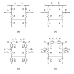
Some new ideas are needed here. There is a clear need for new filter topologies in RF and microwave systems in which stopband energy is absorbed into the circuit rather than reflected back to the source. This need has led to advanced research and development of a novel, patented topology of reflectionless filters. Part 3 of this aritcle will provide an overview of these reflectionless filters.
E.E. World References
- VSWR and impedance, Part 6: Microstrip and stripline
- VSWR and impedance, Part 5: Making a match
- VSWR and impedance, Part 4: Measurements
- VSWR and impedance, Part 3: Implications
- VSWR and impedance, Part 2: Reflected power
- The basics of VSWR and impedance, Part 1
- What’s all this VNA calibration stuff?
- BAW filters keep RF interference out
- An overview of filters and their parameters, Part 4: Time and phase issues
- An overview of filters and their parameters, Part 3: Key parameters
- An overview of filters and their parameters, Part 2: Basic concepts
- An overview of filters and their parameters, Part 1: Context
- Filters, Part 1: Analog, switched, and digital filters
- Filters, Part 2: SAW and BAW devices for RF
- 5G RF filters need more innovation
External References
- Mini-Circuits, “Reflectionless Filter Basics: A Brief History of the Genesis of Reflectionless Filters”
- Mini-Circuits, “Filtering without Reflections: Flattening Multiplier Chain Conversion Efficiency & More“
- Mini-Circuits, X-Series MMC DC to 21 GHz Reflectionless Filters data sheet
- Matthew Morgan, 2015,“Synthesis of a New Class of Reflectionless Filter Prototypes”
- Morgan, Groves, and Boyd, 2018, “Reflectionless Filter Topologies Supporting Arbitrary Ladder Prototypes”
- Microwaves 101, “Reflectionless filters”
- Microwave Journal, “Reflectionless Filters Improve Linearity and Dynamic Range”
- Matthew Morgan, U.S. Patent 8,392.495 B2 (2013), “Reflectionless filters”
- Matthew Morgan, U.S. Patent 10,277,189 B2(2019), ”Transmission line reflectionless filters”