The well-known and extensively analyzed lumped-element bandpass filter is generally not suitable for the RF/microwave region, but there are many distributed-element, energy-based alternatives.
Part 1 of this article established the context for these RF/microwave filters, which operate in the spectrum from several hundred MHz and higher, and increasingly cannot use discrete lumped-circuit elements (RLCs). Instead, they leverage electromagnetic energy principles to achieve bandpass filter objectives. This part looks at some specific technologies and approaches used for these filters, and their relative attributes (although there will always be exceptions and outlier cases).
Note that most RF/microwave filters need to use only L or C elements, or their distributed equivalents since resistive elements increase insertion loss and have other negative consequences. But the inherent resistance of any lumped elements or distributed features must be incorporated into the modeling. Some of these filters need to be tunable by design; for others, their dimensions and frequencies are fixed.
Lumped (discrete) LC filters
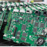
It would be short-sighted to ignore the lumped-element filter, as the underlying filter theory is still valid, and much of it still applies (Figure 1). Lumped-element concepts can be leveraged using non-discrete components to synthesize filters which look and act like LC filters but do not use tangible passive components. Instead, they use a combination of transmission lines, open and short circuits, dielectric gaps, and specialty materials to look like LCs but in a non-lumped, distributed arrangement. They work best when the tolerance in performance specifications is on the relatively larger side since many of the variables of the design cannot be tightly controlled in production.
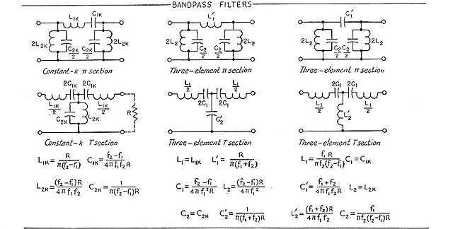
In general, these lumped-element filters have high insertion loss, medium size, power handling range up to about 10 W with smaller components and hundreds of watts with larger ones, and moderate Q of 50 to 200. Since typically ten or more discrete components are needed, the cost and board space requirements are in the mid-range as well.
Cavity and comb filters
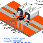
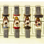
Cavity and comb filters leverage the principles of distributed elements and electromagnetic fields. The cavity filter uses an electronic resonator placed inside a conducting box which encloses the energy. The box has input and output energy-coupling loops (Figure 2). In practice, the box is usually built as a cylinder with a tuning capacitor for adjustability on an axial rod (Figure 3).
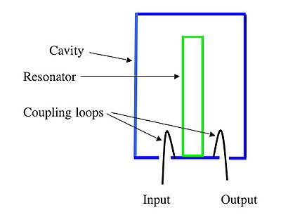
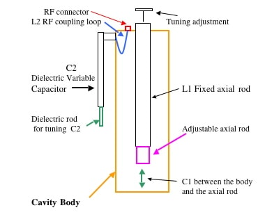
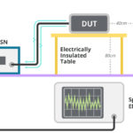
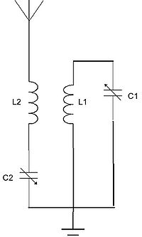
Electrically, the basic cavity-filter equivalent circuit is a simple tuned circuit with L1 and C1 as the cavity body and tuning capacitor, and with L2 and C2 as a tunable, series-LC coupling circuit (Figure 4). The cavity filter has very low insertion loss, is relatively large and can handle tens or hundreds of watts depending on size, is high cost, but has very high Q of over 1000 and even higher.
In a cavity-filter variation, the core elements are multiple rods, which can be modeled as parallel resonant LC circuits; a typical design uses five such rods. The electromagnetic energy from each rod couples to an adjacent rod to yield the desired bandwidth; the rod dimensions determine the center frequency. In a comb-filter variation, the rods are replaced with interdigitated fingers.
(Note that there is a widely used digital-filter equivalent to the comb filter, and which comes in both feed-forward and feedback arrangements. In the former, part of the signal is fed ahead to a stage closer to the output; in the latter, part of the signal is fed back to an earlier stage. Feedforward and feedback arrangements allow for flexibility and tailoring of the characteristics, but is only feasible if the signal is being processed digitally after A/D conversion and also requires considerable computing capacity.)
Part 3 of this article looks at the widely used microstrip filters, as well as ceramic coaxial filters and helical filters.
EE World References
- Basics of bandpass filters
- What are the functions and principles of S-parameters (Part 1)?
- WWhat are the applications and measurements of S-parameters? (Part 2)
- Using the Smith chart for Impedance matching, Part 1
- Impedance matching and the Smith Chart, Part 2
- Printed Circuit Boards, Part 1: Context and phenolic boards
- The basics of FR-4 Printed Circuit Boards
- Printed Circuit Boards, Part 3: Vias and multilayer boards
- Printed Circuit Boards, Part 4: Beyond FR-4
- Filters, Part 2: SAW and BAW devices for RF
External References
- Knowles Capacitors, “Microstrip Filters Deliver Small Size at High Frequencies”
- Skyworks Solutions, Inc., “Glossary of Terms for Coaxial Resonators and Coaxial Inductors”
- Skyworks Solutions, Inc., “Measuring SRF and Q of Coaxial Resonators”
- Skyworks Solutions, Inc., “Characteristic Impedance of Coaxial Resonators”
- Johanson Technology, “SRF & PRF for RF Capacitors”

